Optical disc with different wobble patterns in different grooves
- Summary
- Abstract
- Description
- Claims
- Application Information
AI Technical Summary
Benefits of technology
Problems solved by technology
Method used
Image
Examples
Embodiment Construction
A preferred embodiment of the present invention is described below with reference to the accompanying figures.
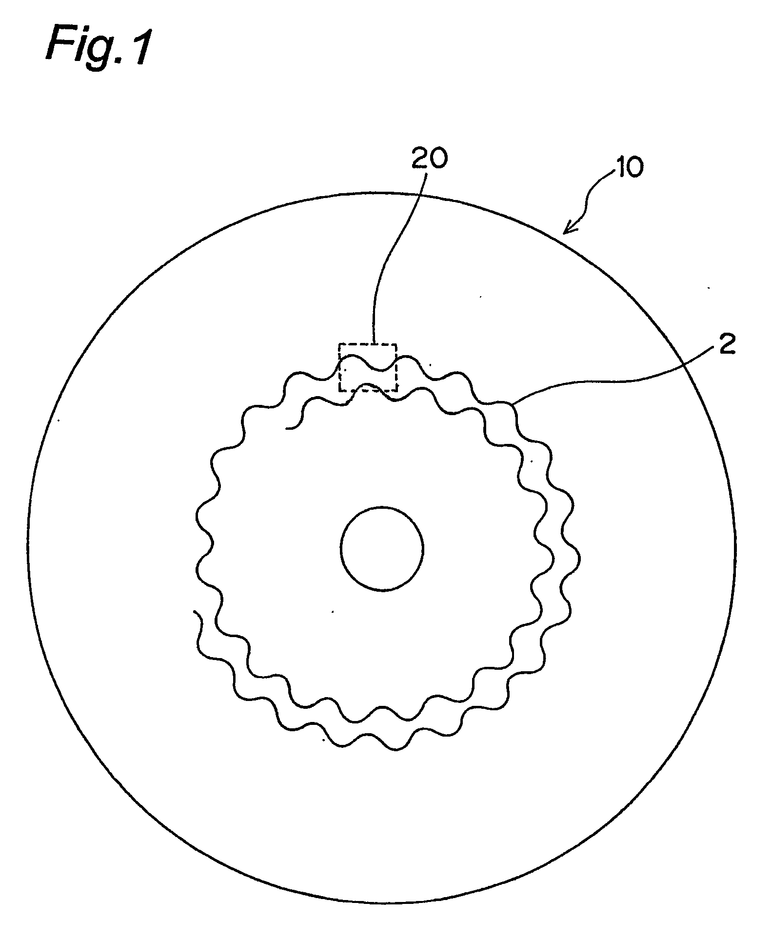
FIG. 1 is a schematic view of an optical disc 10 according to the present invention. Optical disc 10 has plural spiral or concentric tracks 2. In FIG. 1, optical disc 10 with spiral tracks is shown. It will be noted that while the tracks 2 are shown with an extremely large track pitch in FIG. 1, the actual track pitch is, for example, 0.32 μm. Each track 2 is divided into a plurality of sectors, which are used as the data recording and playback unit.
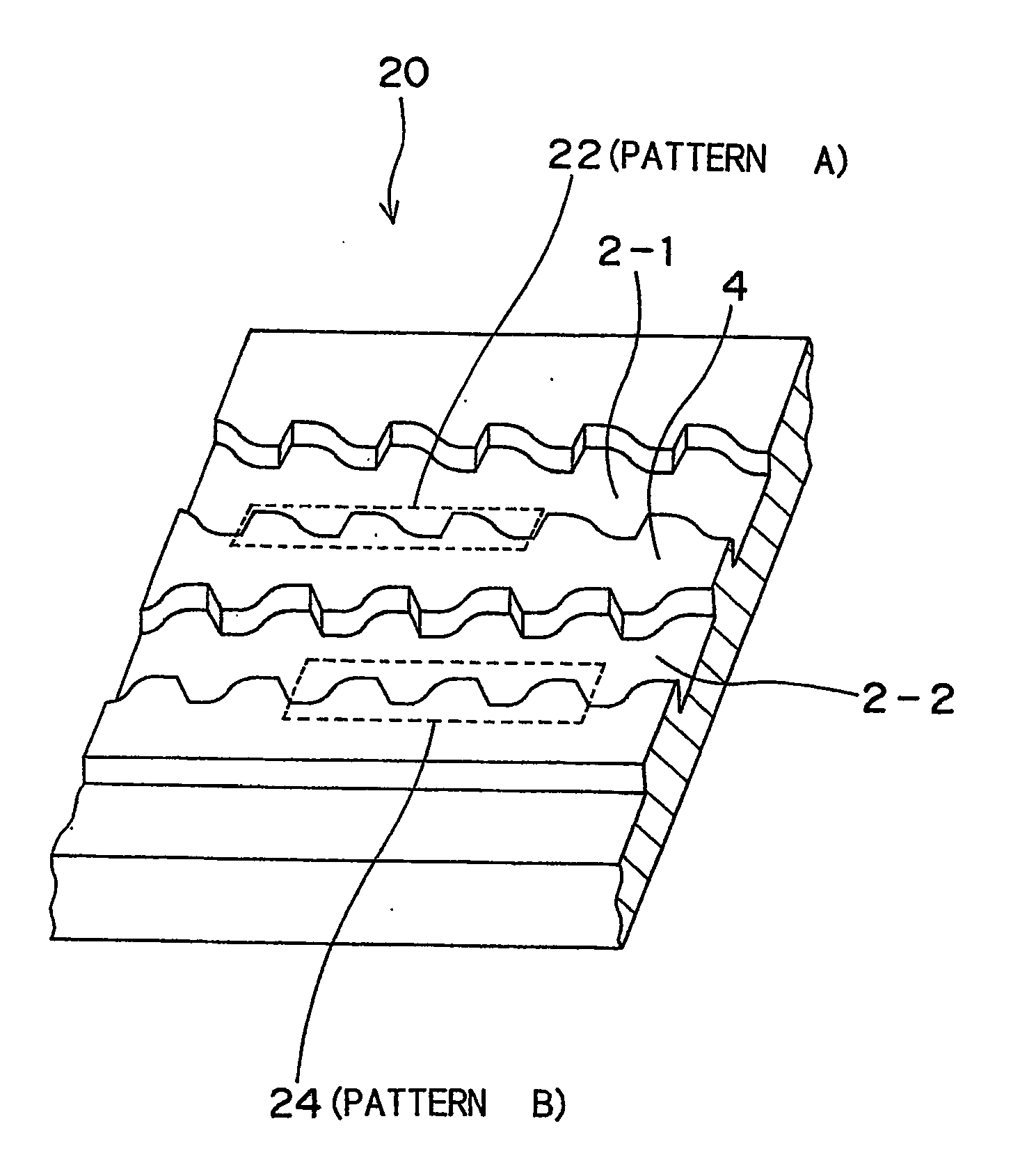
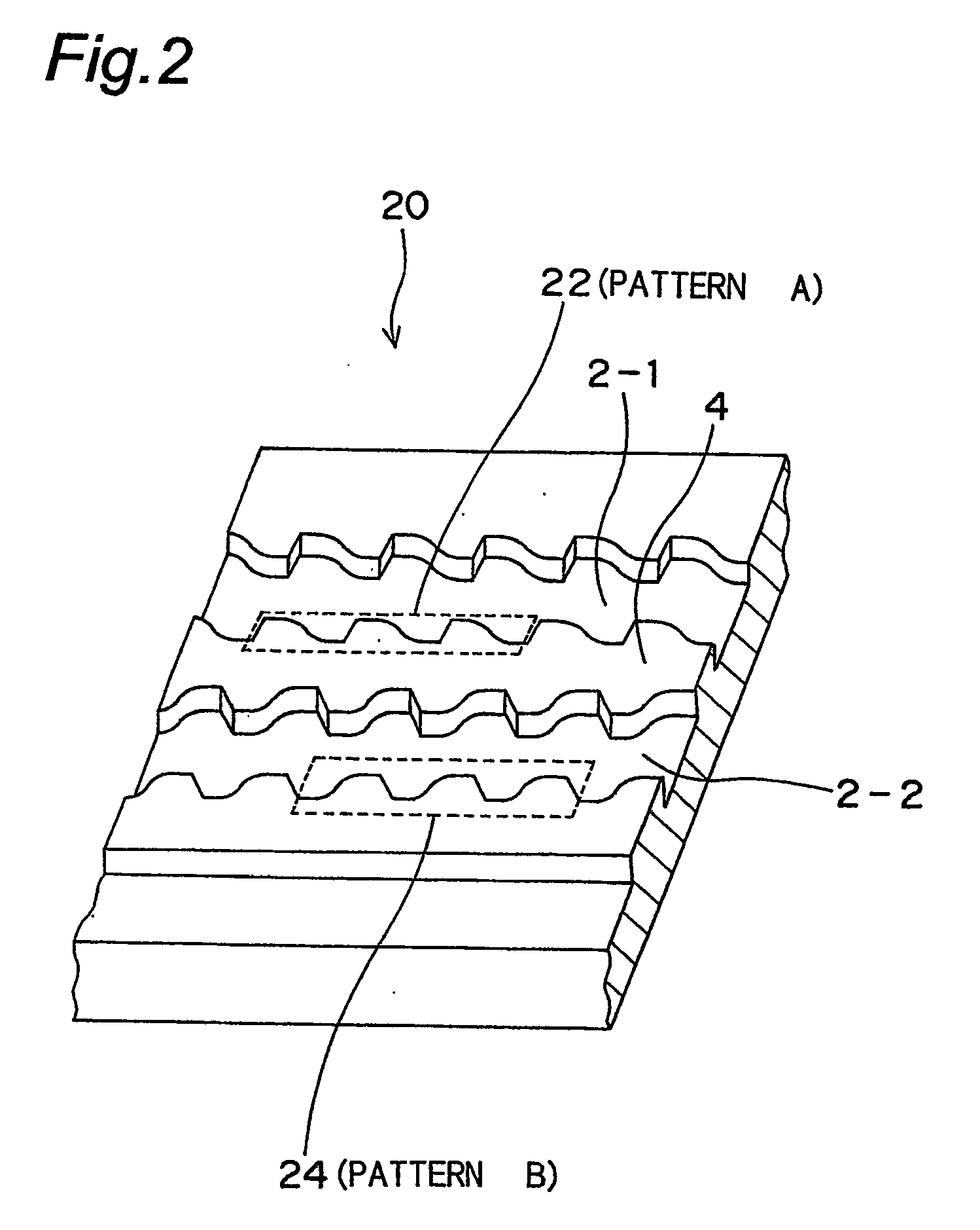
Tracks 2 are defined as grooves formed in optical disc 10 surface. A space between two adjacent track 2 (grooves) is called a land. As will be obvious from FIG. 1, each groove is formed with a wave pattern referred to as a wobble pattern. The present invention uses different wobble patterns to record sector addresses, which are physical addresses used to locate a particular location on optical disc 10.
These wobble patterns ar...
PUM
 Abstract
Description
Claims
Application Information
 - R&D
- Intellectual Property
- Life Sciences
- Materials
- Tech Scout
- Unparalleled Data Quality
- Higher Quality Content
- 60% Fewer Hallucinations
Browse by: Latest US Patents, China's latest patents, Technical Efficacy Thesaurus, Application Domain, Technology Topic, Popular Technical Reports.
© 2025 PatSnap. All rights reserved.Legal|Privacy policy|Modern Slavery Act Transparency Statement|Sitemap|About US| Contact US: help@patsnap.com


