Data-level clock recovery

a clock recovery and data technology, applied in the field of high-speed signaling, can solve the problems of reducing the signaling margin, limiting the data rate of the signaling system, and increasingly non-optimal edge-based cdr results

Active Publication Date: 2005-03-17
K MIZRA LLC
View PDF6 Cites 93 Cited by
  • Summary
  • Abstract
  • Description
  • Claims
  • Application Information

AI Technical Summary

Problems solved by technology

While effective in many applications, edge-based CDR yields increasingly non-optimal results as signaling rates approach and exceed the signal path bandwidth.
As the signaling rate is increased, the transition sampling points grow closer together (i.e., the data eye is compressed in time), pushing the edge-based-CDR sampling point further in the lower-magnitude direction, thereby reducing signaling margin and ultimately limiting the data rate of the signaling system.

Method used


Image

  • Data-level clock recovery
  • Data-level clock recovery
  • Data-level clock recovery

Examples


Embodiment Construction

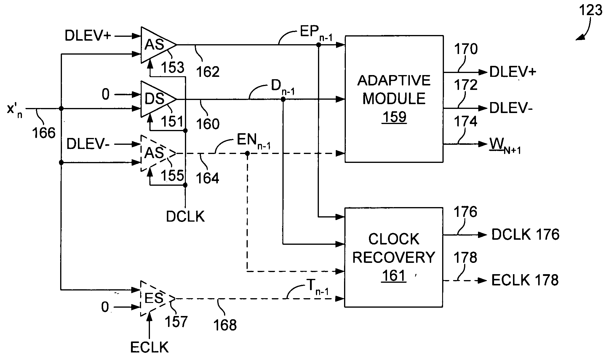
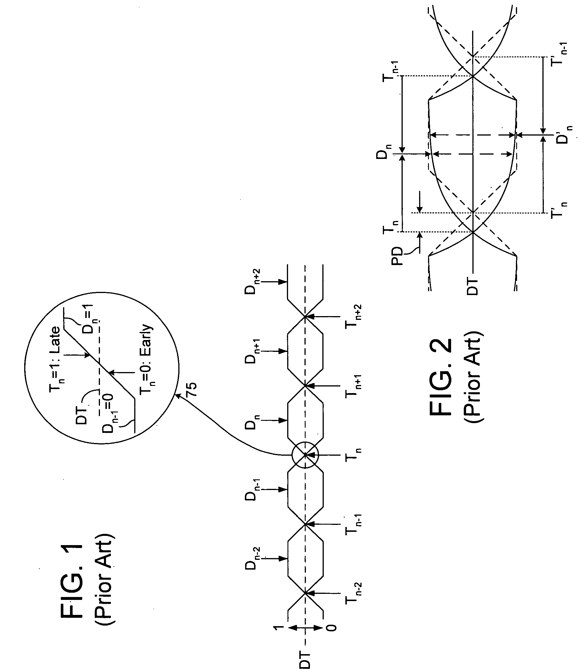
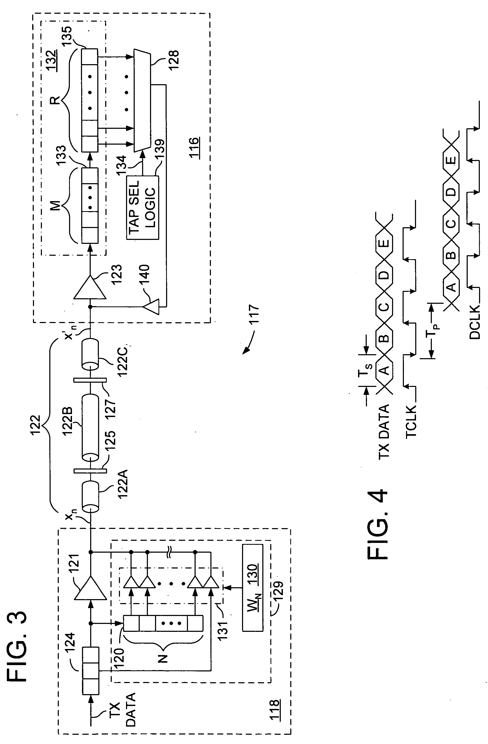
In the following description and in the accompanying drawings, specific terminology and drawing symbols are set forth to provide a thorough understanding of the present invention. In some instances, the terminology and symbols may imply specific details that are not required to practice the invention. For example, the interconnection between circuit elements or circuit blocks may be shown or described as multi-conductor or single conductor signal lines. Each of the multi-conductor signal lines may alternatively be single-conductor signal lines, and each of the single-conductor signal lines may alternatively be multi-conductor signal lines. Signals and signaling paths shown or described as being single-ended may also be differential, and vice-versa. Similarly, signals described or depicted as having active-high or active-low logic levels may have opposite logic levels in alternative embodiments. As another example, circuits described or depicted as including metal oxide semiconducto...


PUM


Abstract

A circuit for adjusting the phase of a clock signal. A first sampling circuit generates a sequence of data samples in response to transitions of the clock signal, each of the data samples having either a first state or a second state according to whether an incoming signal exceeds a first threshold. An second sampling circuit generates an error sample in response to one of the transitions of the clock signal, the error sample having either the first state or the second state according to whether the incoming signal exceeds a second threshold. A phase adjust circuit adjusts the phase of the clock signal if the sequence of data samples matches a predetermined pattern and based, at least in part, on whether the error sample has the first state or the second state.

Description

FIELD OF THE INVENTION The present invention relates generally to high-speed signaling within and between integrated circuit devices, and more particularly to clock recovery in high-speed signaling systems. BACKGROUND Clock-data recovery (CDR) techniques are used to recover both clock and data signals from an incoming data signal. In one prior-art CDR technique, referred to herein as edge-based CDR and illustrated in FIG. 1, a signal receiving circuit samples an incoming data signal at both the midpoint and edges of data eyes (i.e., data valid intervals) to obtain a set of data samples ( . . . Dn−2, Dn−1, Dn, Dn+1, Dn+2, . . . ) and edge samples ( . . . Tn−2, Tn−1, Tn, Tn+1, Tn+2, . . . ), respectively. If the data samples that bound a given edge sample indicate a transition between high and low states, then the edge sample indicates whether the clock edge used to trigger the edge sampling operation occurred early or late relative to the data signal transition, and therefore may b...

Claims


Application Information

Patent Timeline
Patent Type & Authority Applications(United States)
IPC IPC(8): H04L7/00H04L7/033
CPCH04L7/0087H04L7/0337H04L7/0334H04L7/0331
Inventor STOJANOVIC, VLADIMIR M.
Owner K MIZRA LLC
Why Eureka
Try Eureka