Electrically-conductive patterns for monitoring the filling of medical devices

a technology of electrical conductivity and medical devices, applied in the field of diagnostic devices, can solve the problems of diabetes of users and frequent vision impairment, and achieve the effect of easy sens

Inactive Publication Date: 2005-03-17
LIFESCAN IP HLDG LLC
View PDF1 Cites 76 Cited by
  • Summary
  • Abstract
  • Description
  • Claims
  • Application Information

AI Technical Summary

Benefits of technology

The present invention provides a medical diagnostic device that can easily sense when an adequate sample of a conductive biological fluid has been introduced into the device, without relying on the vision of the user. When the device measures glucose concentration, the user generally has diabetes and is frequently vision-impaired.
In another embodiment, the invention provides a method for preparing an element of the diagnostic device. The method is well adapted for a high-speed, continuous line production process.

Problems solved by technology

When the device measures glucose concentration, the user generally has diabetes and is frequently vision-impaired.

Method used


Image

  • Electrically-conductive patterns for monitoring the filling of medical devices
  • Electrically-conductive patterns for monitoring the filling of medical devices
  • Electrically-conductive patterns for monitoring the filling of medical devices

Examples


second embodiment

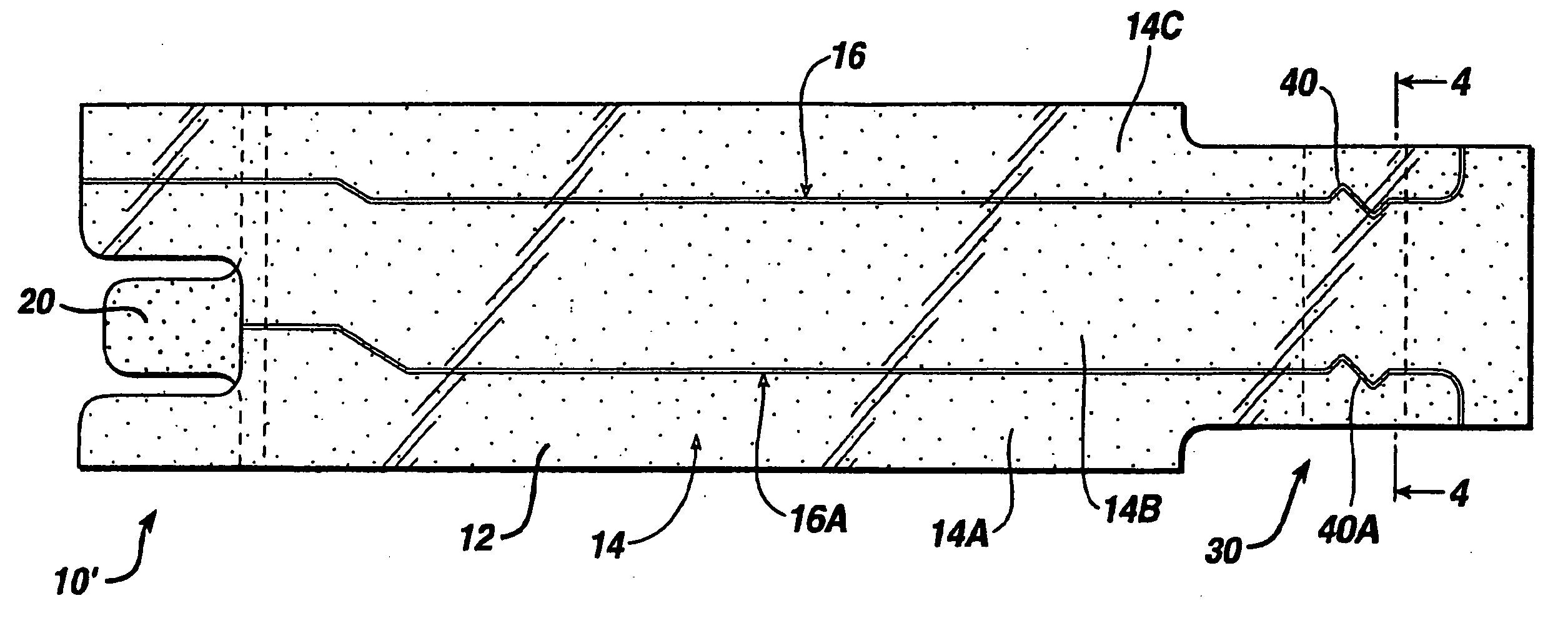
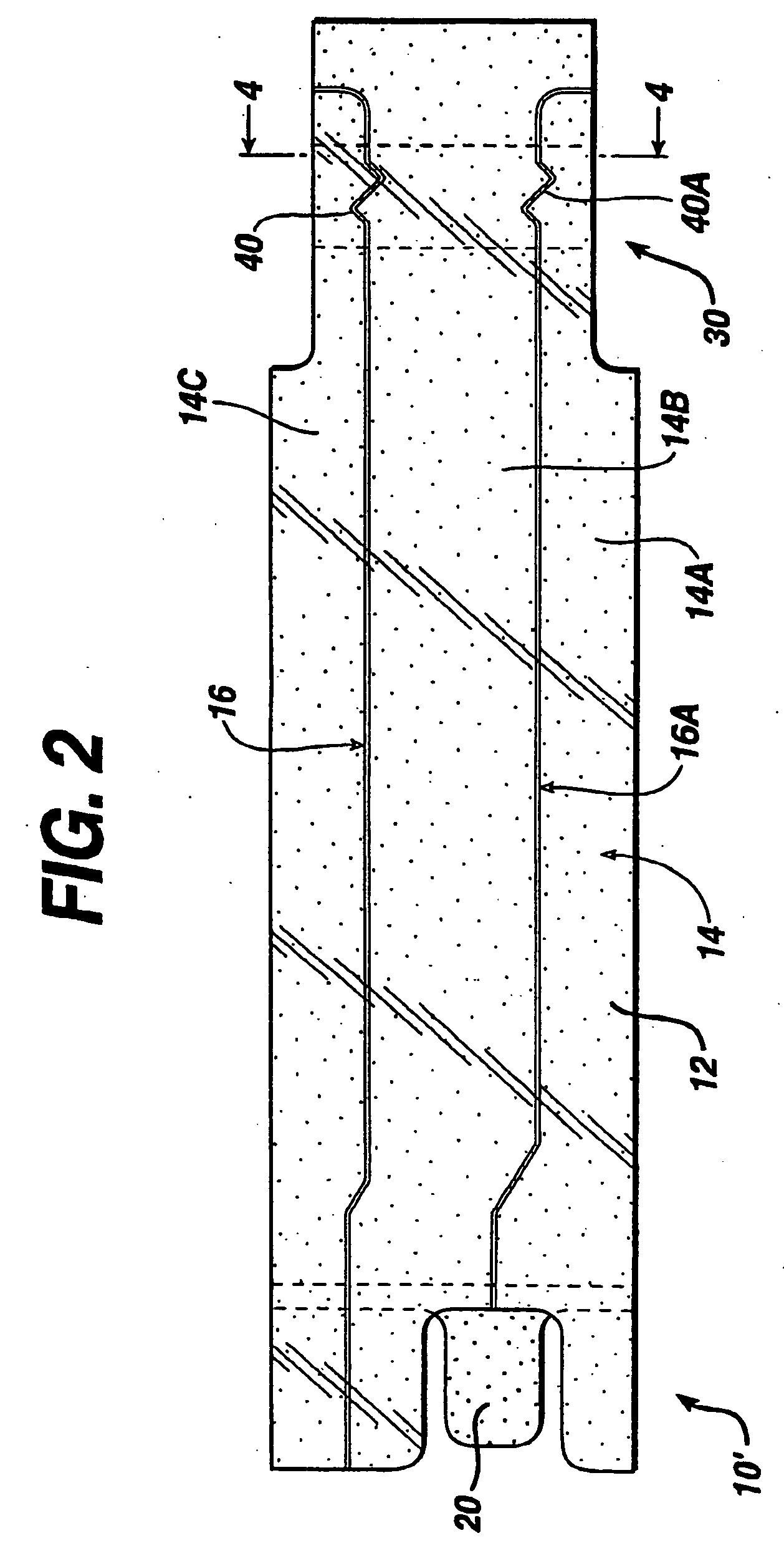
the present invention is a method for providing an electrically-conductive pattern on a conductive-coated flexible insulator, such as sheet 12 of FIG. 2. An apparatus for preparing a pattern such as that designated 16 and 16A in conductive coating 14 is depicted in FIG. 7.

As shown in FIG. 7, web 42, comprising conductive coating 44 on flexible insulator 46 passes between anvil 48 and cutting die 50 to score selected areas of coating 44. The knife regions of die 50 are raised a height h, greater than the thickness of coating 44, so that the cut areas become insulating regions in the coating. However, the knife regions should not be raised so high that the mechanical strength of insulator 46 is undermined. Preferably, the knife height h is about one thousand to ten thousand times the thickness of coating 44, depending on the uniformity and precision of the tooling for cutting. Preferably, as shown, anvil 48 and cutting die 50 are rollers that the web passes between.

Alternative meth...


PUM

PropertyMeasurementUnit
thicknessaaaaaaaaaa
thicknessaaaaaaaaaa
currentaaaaaaaaaa

Abstract

A flexible diagnostic device has a measurement cell that is sandwiched between the conductive surfaces of two conductive-coated insulating layers. At least one of the conductive surfaces is scored with an insulating pattern, so that the flow of a conductive fluid sample into the cell can be monitored.

Description

BACKGROUND OF THE INVENTION 1. Field of the Invention This invention relates to a diagnostic device that has an insulating pattern scored into a conductive coating on the device to facilitate analytical measurements; more particularly, to monitor filling of the device. 2. Description of the Related Art A variety of medical diagnostic procedures involve tests on biological fluids, such as blood, urine, or saliva, to determine an analyte concentration in the fluid. The procedures measure a variety of physical parameters—mechanical, optical, electrical, etc.,—of the biological fluid. Among the analytes of greatest interest is glucose, and dry phase reagent strips incorporating enzyme-based compositions are used extensively in clinical laboratories, physicians' offices, hospitals, and homes to test samples of biological fluids for glucose concentration. In fact, reagent strips have become an everyday necessity for many of the nation's estimated 16 million people with diabetes. Sinc...

Claims


Application Information

Patent Timeline
Patent Type & Authority Applications(United States)
IPC IPC(8): G01N27/327G01N33/487G01N27/416G01N27/49G01N33/483
CPCG01N27/3272G01N33/48
Inventor SHARTLE, ROBERT JUSTICEOHARA, TIMOTHY J.KERMANI, MAHYAR Z.
Owner LIFESCAN IP HLDG LLC
Why Eureka
Try Eureka