Delivery system for medical devices

a delivery system and medical device technology, applied in the field of medical device delivery systems, can solve the problems of inaccurate positioning of stents, and prior art delivery systems, and achieve the effects of simple system operation, accurate placement, and minimal movement during device deploymen

Inactive Publication Date: 2005-03-17
ABBOTT VASCULAR SOLUTIONS
View PDF29 Cites 329 Cited by
  • Summary
  • Abstract
  • Description
  • Claims
  • Application Information

AI Technical Summary

Benefits of technology

[0011] The present invention is directed to a delivery system for delivering and more accurately deploying a medical device, such as a stent, to the target site in a body lumen. The delivery system in accordance with the present invention incorporates unique features which facilitates minimal movement during device deployment, accurate placement, and single-handed system operation. While the delivery system can be used to deploy any self-expanding stent, it also can be used to deploy other self-expanding medical devices, including medical devices which are not self-expanding as well.
[0012] In one aspect of the present invention, the delivery system include a control handle and a catheter portion which is designed for advancement to a target area in a patient's body lumen over a deployed guide wire using “over the wire” techniques known in the art. The catheter portion includes an inner catheter member having a proximal portion attached within the control handle and a distal portion upon which the medical device is mounted in a collapsed position. An outer restraining member extends over the inner catheter member in a coaxial arrangement. The outer restraining member holds the medical device in the collapsed position until the device is to be deployed. If the medical device is not self-expanding, the outer restraining member does not necessarily restrain the device, but provides a protective cover for the device. The outer restraining member is retractable to release the medical device by a retraction mechanism housed in the control handle. The control handle includes a rotatable thumbwheel which is easily moveable to provide a manual mechanism for retracting the restraining sheath. The control handle immobilizes the inner catheter member, preventing it from moving relative to the outer restraining member during deployment. The control handle allows the delivery system to be operated by just one hand, freeing the physician's other hand for other purposes, such as stabilizing the guiding catheter during deployment of the medical device.
[0013] In one aspect of the present invention, the catheter portion includes an outer sheath which is utilized to stiffen the catheter portion of the delivery system on that the inner catheter member will not change shape outside the body when the outer restraining member is retracted to deploy the medical device. The outer sheath extends at least partially over the length of the outer restraining member in a coaxial relationship in order to create a conduit between the control handle and the point of insertion into the patient. This outer sheath helps to reduce frictional forces which may be created with the medical device that is inserted into the patient to obtain entry for the catheter portion, such as a rotating hemostatic valve (RHV), or other similar device, and helps to prevent the inner catheter member from moving distally as the outer restraining sheath is being retracted via the control handle.
[0015] In another aspect of the present invention, the retraction mechanism of the control handle allows the outer restraining member to be retracted in a proximal direction only and includes a stop mechanism which prevents the retraction mechanism from prematurely deploying. The control handle allows the physician to actuate the retraction mechanism using a simple thumb motion on the thumbwheel which helps to prevent unwanted forces from acting on the control handle which can typically be developed when a pistol-like actuated control handle is utilized. As a result, a more accurate placement of the medical device may be achieved.

Problems solved by technology

One of the difficulties encountered in using prior art stents involve maintaining the radial rigidity needed to hold open a body lumen while at the same time maintaining the longitudinal flexibility of the stent to facilitate its delivery and accommodate the often tortuous path of the body lumen.
However, problems have been associated with such prior art delivery systems.
For example, systems which rely on a “push-pull design” or “push-back design” can experience unwanted movement of the collapsed stent within the body vessel when the inner member is pushed forward which can lead to inaccurate stent positioning.
This change of the geometry of the system within the anatomy can lead to inaccurate stent positioning.
Failure to do so may result in deploying the stent beyond the target area and can cause the stent to bunch up.
When the outer sheath is retracted proximally into the deployment handle during deployment, the length of the exposed outer sheath tends to shorten.
However, the outer sheath tends to shorten during deployment, thus changing the shape of the exposed portion of the catheter.
As a result, the movement of the inner catheter member caused by the retraction of the outer sheath can cause the stent to deploy prematurely and at a location beyond the targeted site.
As a result, less than accurate deployment of the stent can occur.
However, if the delivery system is not kept straight during deployment, then the inner catheter member has this tendency to move distally during deployment.
The above-described stent delivery systems also can be somewhat difficult to operate with just one hand, unless a mechanical advantage system (such as a gear mechanism) is utilized.
Even a slight axial movement of the catheter assembly during deployment can cause some inaccurate placement of the stent in the body lumen.
In doing so, the physician usually creates a backwards force on the delivery system which also can cause the catheter portion of the delivery system to move within the patient's vasculature, resulting in less than accurate placement of the stent within the patient.
Also, some of these stent delivery systems have a limited range of retraction of the outer sheath which can limit the use of the delivery system to smaller medical devices which require only a small amount of retraction in order to expand the device.
Larger medical devices, such as vasculature grafts, cannot be deployed because the control handle of the system cannot retract the outer sheath a sufficient length in order to expose the entire graft.

Method used


Image

  • Delivery system for medical devices
  • Delivery system for medical devices
  • Delivery system for medical devices

Examples


Embodiment Construction

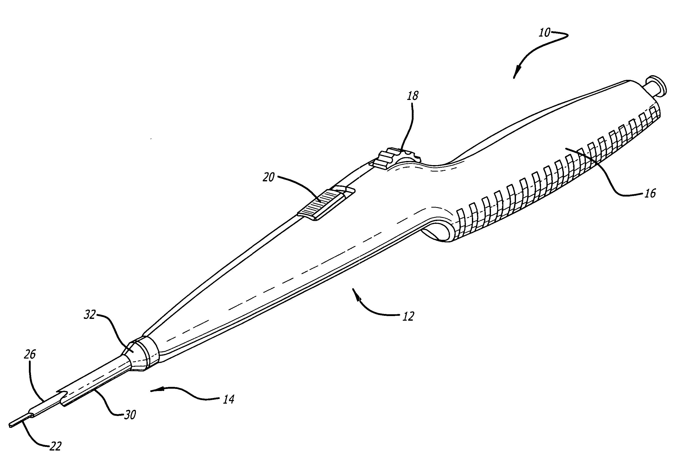
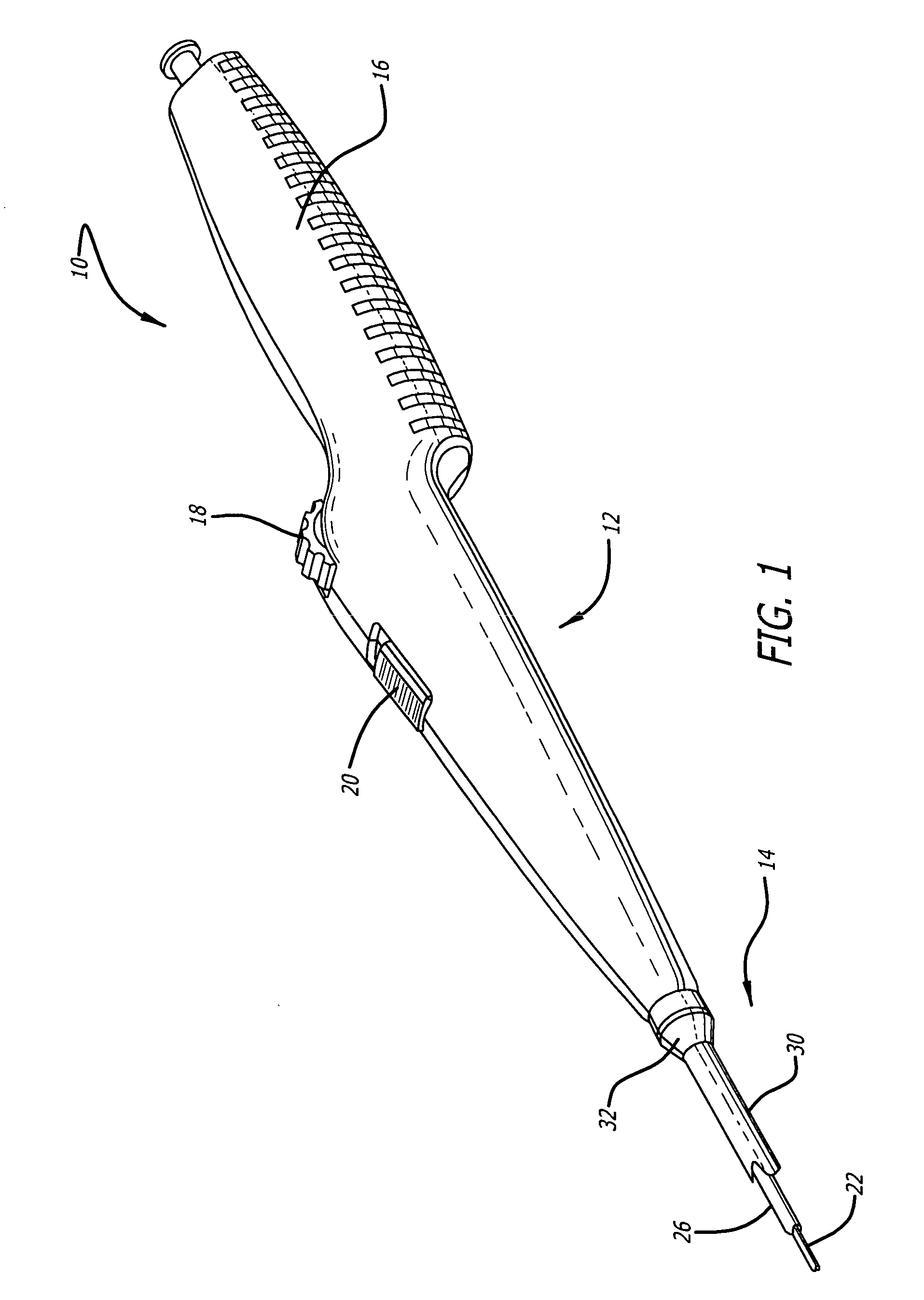
[0025] The present invention relates to a delivery system for delivering and deploying a medical device into a target site in a patient's body, such as a body lumen. For sake of illustration, the following exemplary embodiments are directed to a delivery system for delivering and deploying a self-expanding stent, although it is understood that the present invention is applicable to other medical devices which are implantable in a body lumen as well as other parts of the body. Additionally, the medical device can be either a self-expanding device or a non self-expanding device.

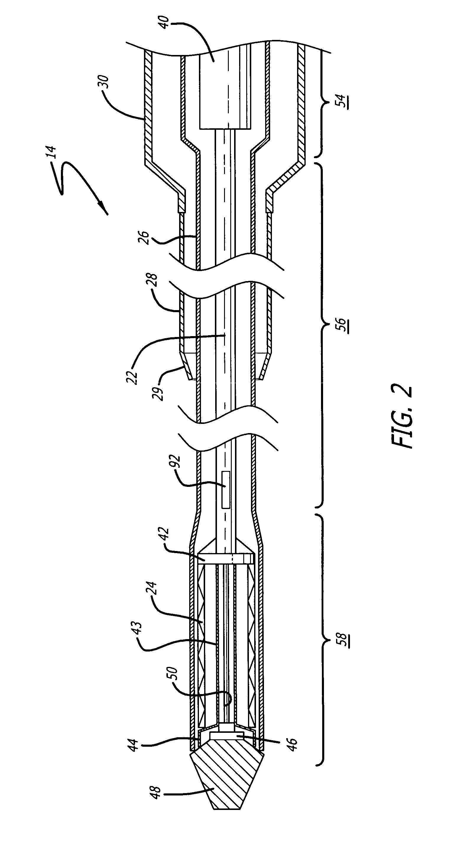
[0026] Referring now to FIGS. 1 and 2, in one particular embodiment of the present invention, the delivery system 10 incorporating features of the present invention includes a control handle 12 and a catheter portion 14. As can best be seen in FIG. 1, the control handle includes a hand portion 16 which allows the physician to hold the control handle utilizing one hand. The control handle 12 also includes a rot...


PUM


Abstract

The invention is directed a delivery system for implantation a self-expanding medical device in a body which includes a control handle and a catheter portion. The catheter portion includes an outer restraining member which covers the collapsed, medical device, an inner catheter member having a distal end including a region upon which the medical device is mounted, and an outer sheath which is removably attached to the control handle. The outer sheath creates a conduit for the catheter portion to prevent the inner catheter member from moving axially when the outer restraining member is retracted. The control handle has a rotatable thumbwheel to actuate a retraction mechanism attached to the proximal end of the outer restraining member which moves the restraining member in a proximal direction to deploy the medical device.

Description

BACKGROUND OF THE INVENTION [0001] The present invention relates generally to delivery systems for delivering and deploying medical devices, such as stents, which are adapted to be implanted into a patient's body, such as a blood vessel and, more particularly, to a delivery system for more accurately deploying a self-expanding medical device into an area of treatment. [0002] Stents are generally cylindrically shaped devices which function to hold open and sometimes expand a segment of a blood vessel or other arterial lumen, such as coronary artery. Stents are usually delivered in a compressed condition to the target site and then deployed at that location into an expanded condition to support the vessel and help maintain it in an open position. They are particularly suitable for use to support and hold back a dissected arterial lining which can occlude the fluid passageway there through. Stents are particularly useful in the treatment and repair of blood vessels after a stenosis has...

Claims


Application Information

Patent Timeline
Patent Type & Authority Applications(United States)
IPC IPC(8): A61F2/06A61F2/84
CPCA61F2/95A61M2025/0098A61F2002/9517A61F2/966A61F2/9517
Inventor WU, PATRICK P.FITZGERALD, KEIFYAMBAO, AUGUSTGREEN, MICHAEL
Owner ABBOTT VASCULAR SOLUTIONS
Why Eureka
Try Eureka