Locking anti-motion suspension

a technology of anti-motion suspension and locking cylinder, which is applied in the direction of loading/unloading vehicle arrangment, transportation items, transportation packaging, etc. it can solve the problems of large rear tires, large height, and inability to easily go through doorways or apertures of buildings that are under construction, and achieve the effect of effective locking of the cylinder

Active Publication Date: 2005-03-24
CNH IND AMERICA LLC +1
View PDF6 Cites 42 Cited by
  • Summary
  • Abstract
  • Description
  • Claims
  • Application Information

AI Technical Summary

Benefits of technology

[0035] The lock / suspend valve may effectively lock the cylinder when it disconnects the accumulator from the cylinder.

Problems solved by technology

Backhoes with their large rear tires and wide stance cannot easily go through doorways or apertures of buildings that are under construction.
Furthermore, their stance is typically too wide to pass through the doorways and their height as well is too large, typically on the order of 10-12 feet off the ground—too large to pass through building doorways or wall openings.
This would require an extremely large area in which to turn around, and they would be dangerous in crowded work areas.
Another common feature to skid steer vehicles is their rigid suspension which limits their speed on rough ground.
The inherent pitching and rocking causes operator discomfort, loss of vehicle stability, loss of material in the bucket, and potential for catching on to low-hanging obstructions found in buildings under construction, such as beams, electrical wiring, HVAC conduits and the like.
Doorways that were previously passable can interfere with the chassis or other components fixed to and extending therefrom, such as the operator's compartment cage.
In this position, lower chassis components are at greater risk of inadvertently hitting the ground or protrusions therefrom.
Similarly, when the bucket is unloaded, the chassis raises and upper portions of the chassis and such elements as operator compartment cages may extend upward and interfere with the top of doorways through which the vehicle passes.
This continual checking process, especially when a suspended skid steer vehicle is operated in a confined space such as a building on a construction site, can be difficult.
As a result, operators tend to drive slower and approach potential obstructions and restricted spaces at much slower speeds, not just when they initially maneuver around the obstacles, but each and every time they approach them, since the height of the chassis may have changed.

Method used


Image

  • Locking anti-motion suspension
  • Locking anti-motion suspension
  • Locking anti-motion suspension

Examples


Embodiment Construction

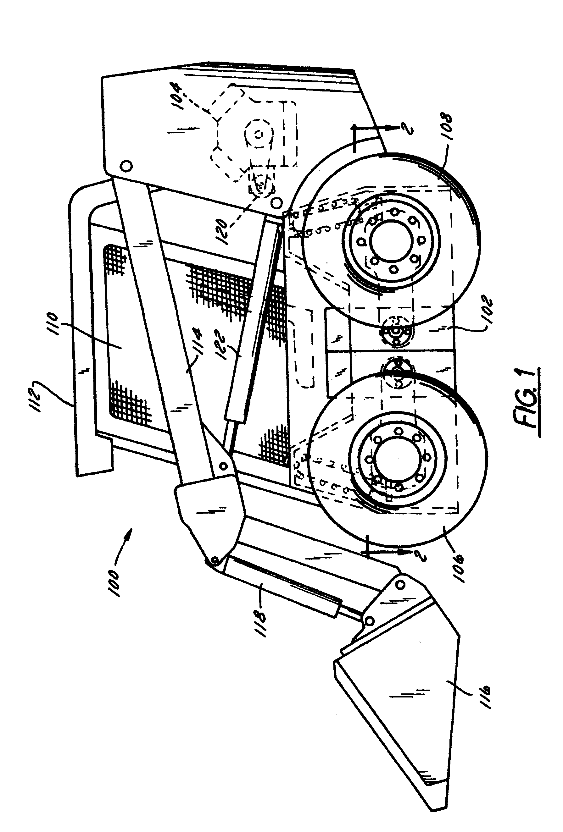
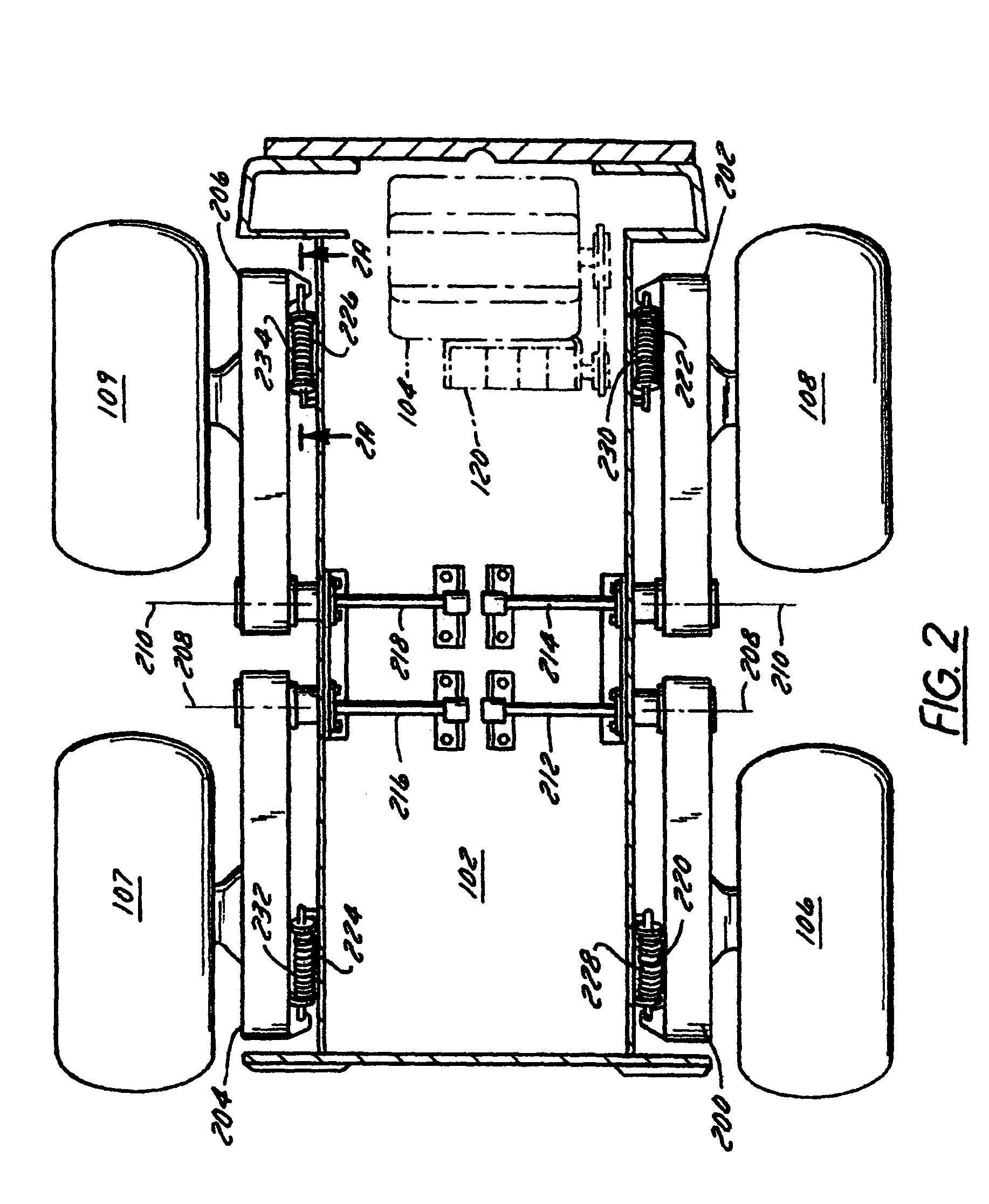
[0052]FIGS. 1 and 2 show a skid steer vehicle 100 that has a chassis 102, an engine 104 mounted on the chassis, four wheels including left-side wheels 106, 108 and right-side wheels 107 and 109 (FIG. 2), an operator compartment 110 surrounded by a roll-over protection system 112, a pair of loader lift arms (left-side arm 114 shown in FIG. 1), a loader implement here shown as bucket 116, at least one (and preferably two) bucket cylinder 118, and at least one (and preferably two) loader arm lift cylinder 122.

[0053] The wheels 106, 107, 108, and 109 may have solid or pneumatic tires. The wheels need not contact the ground directly, but may be wrapped by continuous belts or tracks (not shown). One of these tracks may extend around wheels 106 and 108 on one side of the vehicle and be driven thereby. The other track may extend around wheels 107 and 109 on the other side of the vehicle and be driven thereby.

[0054] The operator compartment 110 is preferably defined by a cage, having a pla...


PUM


Abstract

A skid steer vehicle has a suspension that includes a control arm pivotally coupled to the vehicle chassis that is supported by a hydraulic cylinder connected to an accumulator to provide springing. A hydraulic circuit coupled to the cylinder and accumulator permit the operator to raise and lower the chassis, to lock the suspension while the vehicle is loaded, and to automatically charge or discharge the accumulator to match the cylinder pressure during loading and unloading. In this manner, when the suspension is unlocked after loading, the vehicle chassis neither rises nor falls.

Description

FIELD OF THE INVENTION [0001] The invention relates generally to skid steer vehicles. More particularly, it relates to suspensions for such vehicles. Even more particularly, it relates to suspensions for skid steer vehicles that lock and release. BACKGROUND OF THE INVENTION [0002] Skid steer loaders were first invented about 30 years ago to fill a need for a small highly maneuverable vehicle that was capable of carrying an implement mounted on loader arms. Skid steer loaders are typically small vehicles, on the order of 10 to 14 feet long, that rest on four or more wheels, at least two of which being disposed on each side of the vehicle. [0003] In order to turn these vehicles, the wheels on opposing sides of the skid steer loader are driven at different speeds. This causes the faster moving wheels on one side to advance that side over the ground faster than the other side on slower moving wheels. The effect is to turn the vehicle toward the wheels on the slower moving side. Since th...

Claims


Application Information

Patent Timeline
Patent Type & Authority Applications(United States)
IPC IPC(8): B60G11/26B60G17/00B60G17/005B60G17/056
CPCB60G17/005B60G2300/022B60G2202/154B60G17/056
Inventor SHORE, DANIEL B.
Owner CNH IND AMERICA LLC
Why Eureka
Try Eureka