Liquid crystal display device

a liquid crystal display and display device technology, applied in the direction of identification means, instruments, details of portable computers, etc., can solve the problems of hammering the reduction of cost in the manufacture of liquid crystal displays

Inactive Publication Date: 2005-03-24
PANASONIC LIQUID CRYSTAL DISPLAY CO LTD +1
View PDF9 Cites 73 Cited by
  • Summary
  • Abstract
  • Description
  • Claims
  • Application Information

AI Technical Summary

Benefits of technology

[0027] Accordingly, it is an object of the present invention to solve the various problems mentioned above related arts and to provide a liquid crystal display device which can provide reliable positioning and secure holding of the optical sheet relative to the lower frame by use of a positioning guide on the liquid crystal panel and positioning means on the optical sheet in common, whereby the liquid crystal display device can have a structure which is capable of suppressing the removal or disengagement of the optical sheet assembled on the lower frame at the time of transporting the assembly or at the time of transferring it, so as to reduce man-hours for assembling and simplify the operation and reduce the manufacturing cost.
[0056] Due to the above-mentioned respective constitutions, the positioning and the holding of the optical sheet onto the lower frame (mold case) can be reliably performed, and, at the same time, this function can be also serve as a guide for positioning the liquid crystal panel, which is mounted on the optical sheet in a superposed manner, so that the removal or the disengagement of the optical sheet at the time of conveying or transporting the lower frame into which the optical sheet is incorporated can be suppressed. Further, since the man-hours for assembling can be reduced, the operation is simplified and the manufacturing cost can be reduced.
[0069] In this embodiment, the above-mentioned first columnar member is formed into a size which can face the side surface of the liquid crystal panel in an opposed manner, and a portion (portion A) which faces the side surface of the liquid crystal panel in an opposed manner is projected to the side surface side of liquid crystal panel more than the other portion (portion B) which is fitted into the first opening. For example, when the first columnar member is formed into a circular columnar shape, the radius of the portion A is made larger than the radius of the portion B. Due to such a constitution, the positioning of the liquid crystal panel in the assembling step of the liquid crystal display device can be performed promptly and reliably.
[0073] Due to such a constitution, the position (height measured by using the bottom surface of the first frame as a reference) of the joining portion between the first columnar member and the first frame, and such a position of the optical sheet, can be aligned so that the stress and the distortion which is applied to the optical sheet at the time of fixing the optical sheet to the first frame at the first columnar member can be reduced.
[0074] Although the bank which is referred to here may be formed as a wall which surrounds the bottom surface of the first frame, the bank may be intermittently formed in conformity with openings formed in the bottom surface to enable heat radiation from the first frame or to make the first frame more light-weight.
[0108] To the contrary, according to one example of the present invention, by elongating the second opening along the second periphery, the conventional deflection of the optical sheet derived from a positional displacement between the second columnar member and the second opening into which the second columnar member is inserted, such as caused by expansion of the optical sheet, can be prevented. Accordingly, the optical problem caused by the deflection of the optical sheet can be eliminated.

Problems solved by technology

Further, the use of such a metallic clip CLM becomes one of the obstacles which hampers the reduction of cost in the manufacture of the liquid crystal display.

Method used


Image

  • Liquid crystal display device
  • Liquid crystal display device
  • Liquid crystal display device

Examples


first embodiment

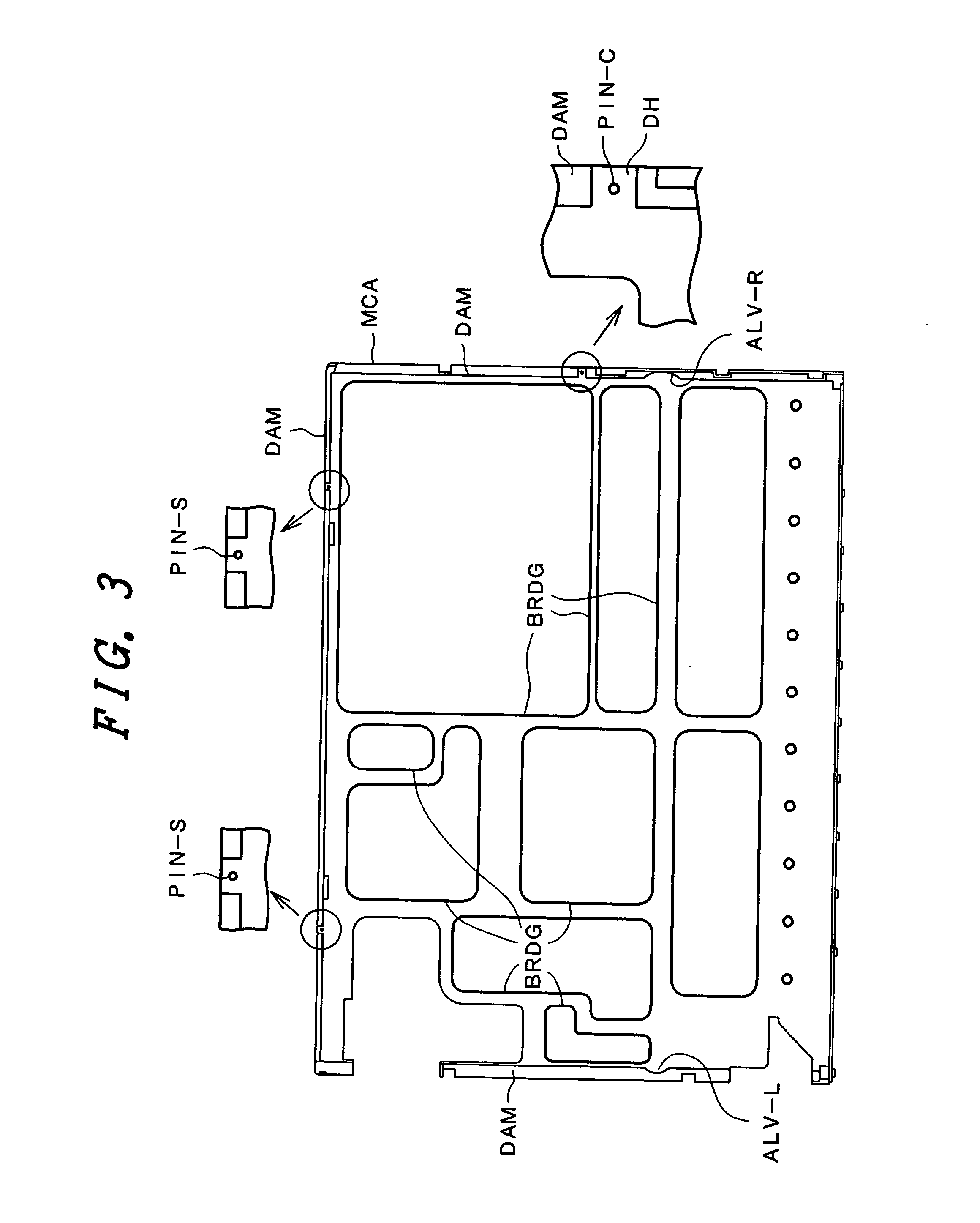
[0140]FIG. 3 is a plan view of a lower frame used in the liquid crystal display device according to the present invention. The drawing shows a plan view as seen from the liquid crystal panel side. The lower frame MCA of this embodiment has an approximately rectangular shape with a bank portion DAM which has a height at an upper frame side formed on the periphery thereof. A linear lamp (cold cathode fluorescent tube) which constitutes a backlight is arranged at the lower side of FIG. 3, while a gate driver side and a drain driver side are arranged at the left side and the lower side of FIG. 3, respectively.

[0141] Respective sides of the lower frame MCA are connected to each other by a plurality of crosspieces BRDG which are arranged so as to take the mechanical strength and the heat radiation into account. Engaging recessed portions ALV-R, ALV-L of the lower frame MCA, which are formed in the bank portion DAM at left and right sides which intersect the lower side on which the linear ...

third embodiment

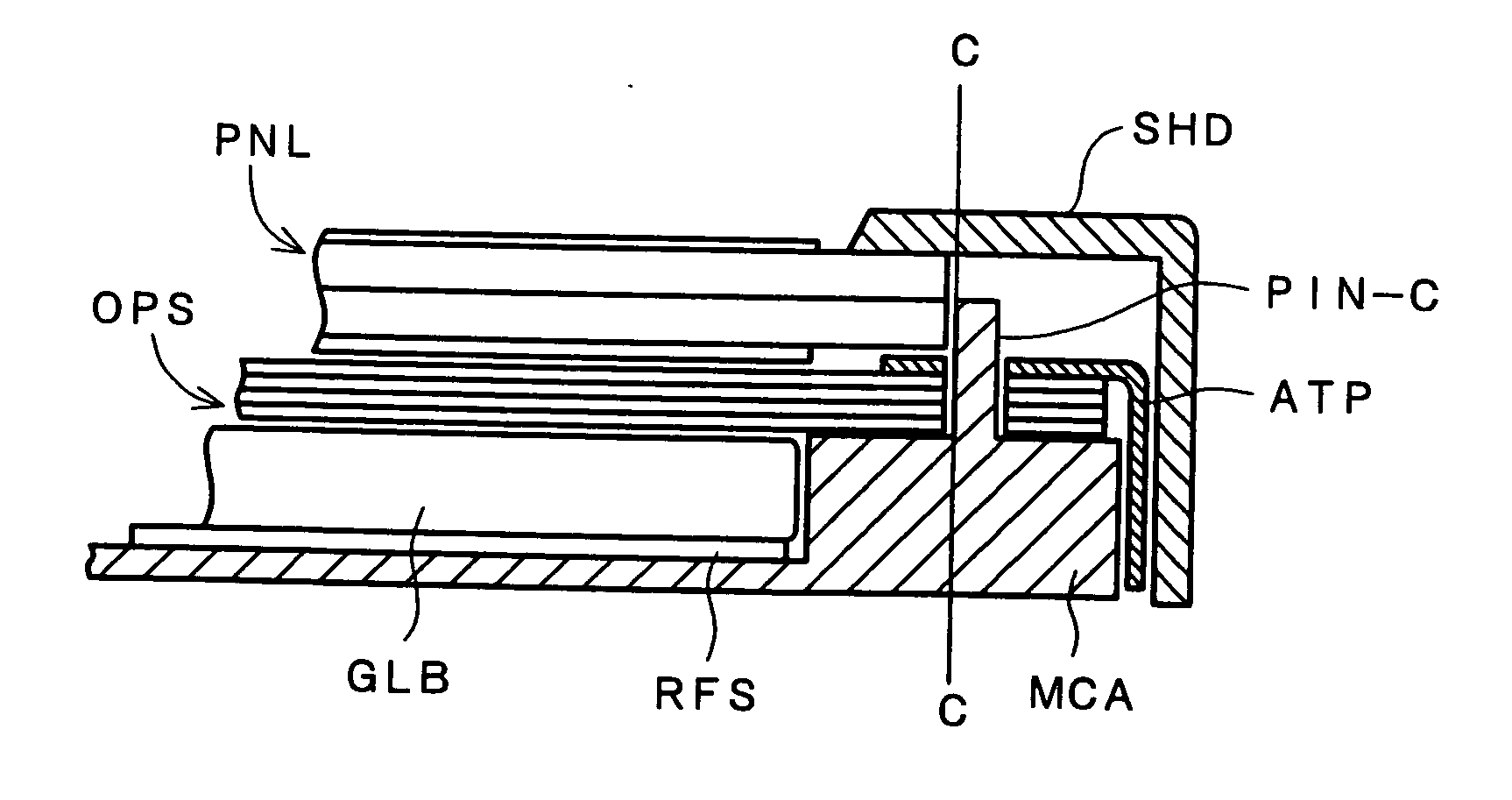
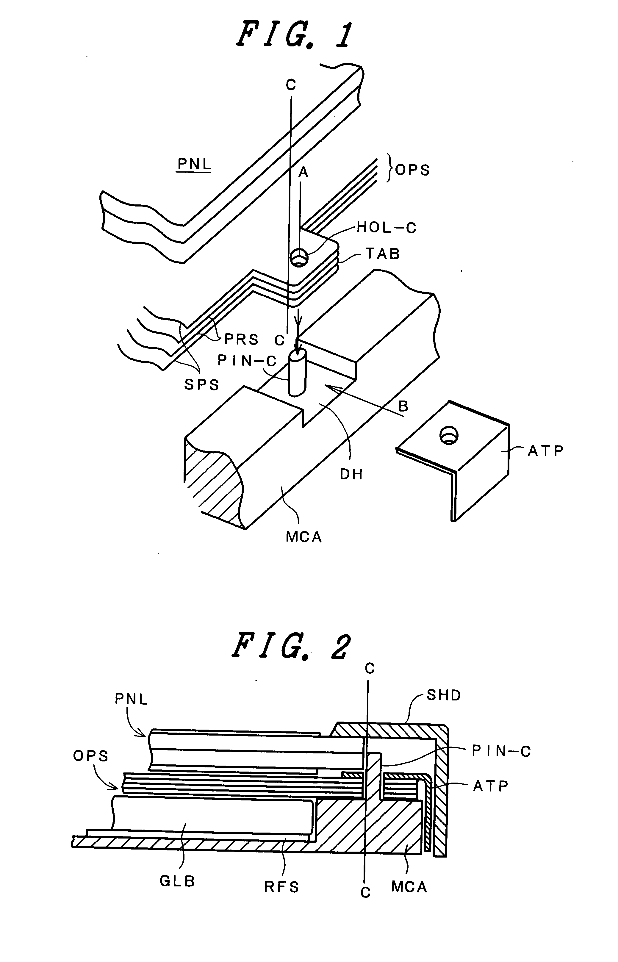
[0169]FIG. 14 is a cross-sectional view of a liquid crystal display device after constitutional members are assembled to illustrate the liquid crystal display device according to the present invention. In this embodiment, a cylindrical sleeve SB, similar to the above-mentioned cylindrical sleeve SB, which was described in conjunction with FIG. 17A and FIG. 17B, is fitted on the columnar member PIN-C of the lower frame MCA, which described in conjunction with FIG. 2, thus fixing the optical sheet OPS to the columnar member PIN-C such that the optical sheet OPS is not disengaged from the columnar member PIN-C.

[0170] The cylindrical sleeve SB can be made to function as a positioning guide for the liquid crystal panel PNL by changing the diameter of the cylindrical sleeve SB. Further, by changing the size of the cylindrical sleeve SB or by adjusting the extent of protrusion a wall of a side surface thereof which faces the liquid crystal panel PNL in an opposed manner, it becomes possibl...


PUM

PropertyMeasurementUnit
lengthaaaaaaaaaa
brightness distributionaaaaaaaaaa
transparentaaaaaaaaaa

Abstract

In a liquid crystal display device, a recessed portion is formed in a portion of a periphery of a lower frame, a columnar member is provided to the recessed portion, the columnar member is allowed to pass through a hole formed in a projecting portion which is provided on an optical sheet, and a side surface of a liquid crystal panel is brought into contact with the columnar member. The columnar member provided on the lower frame not only determines the position of the liquid crystal panel with respect to the lower frame, but also determines the position of the optical sheet with respect to the lower frame and firmly holds the optical sheet onto the lower frame, thus preventing the disengagement of the optical sheet from the lower frame.

Description

CROSS-REFERENCE TO RELATED APPLICATIONS [0001] This application is a continuation of application Ser. No. 10 / 020,976 filed on Dec. 19, 2001. The contents of application Ser. No. 10 / 020,976 are hereby incorporated herein by reference in their entirety.BACKGROUND OF THE INVENTION [0002] The present invention relates to a liquid crystal display device; and, more particularly, the invention relates to a liquid crystal display device in which the reliability is enhanced by holding an optical sheet that is interposed between a liquid crystal panel and a backlight, which is arranged at a back surface of the liquid crystal panel, at a given position in such a way as to prevent a positional displacement of the optical sheet. [0003] A liquid crystal display device, which is capable of generating a color display of high definition for a notebook type computer or a computer monitor, is provided with a light source for illuminating the liquid crystal panel from a back of the panel (a so-called b...

Claims


Application Information

Patent Timeline
Patent Type & Authority Applications(United States)
IPC IPC(8): G02F1/1333G02F1/13G02F1/13357G06F1/16G09F9/00
CPCG02F1/133308G02F1/133504G02F1/13452G02F2001/133314G06F1/1637G02F2001/133325G02F2201/46G06F1/1616G02F2001/133322G02F1/133314G02F1/133322G02F1/133325G02F1/1333G02F1/1335
Inventor FUKAYAMA, NORIHISA
Owner PANASONIC LIQUID CRYSTAL DISPLAY CO LTD
Why Eureka
Try Eureka