Optical fiber pressure and acceleration sensor fabricated on a fiber endface

a fiber endface and fiber optic technology, applied in the direction of fluid pressure measurement, interferometer, instruments, etc., can solve the problems of severe constraints on sensor design and material composition, the pressure sensor for these locations must be very small, and the conventional fiber optic pressure sensor design is typically not suitable for extreme environments

Inactive Publication Date: 2005-03-24
VIRGINIA TECH INTPROP INC
View PDF4 Cites 99 Cited by
  • Summary
  • Abstract
  • Description
  • Claims
  • Application Information

AI Technical Summary

Benefits of technology

[0008] The present invention includes an optical fiber pressure sensor having an optical fiber with an endface, and a hollow tube bonded to the endface. A pressure-sensitive diaphragm is bonded to the opposite end

Problems solved by technology

Also, pressure sensors for these locations must be very small since space is limited.
These requirements impose severe constraints on the sensor design and material composition.
Conventional fiber optic pressure

Method used


Image

  • Optical fiber pressure and acceleration sensor fabricated on a fiber endface
  • Optical fiber pressure and acceleration sensor fabricated on a fiber endface
  • Optical fiber pressure and acceleration sensor fabricated on a fiber endface

Examples


Embodiment Construction

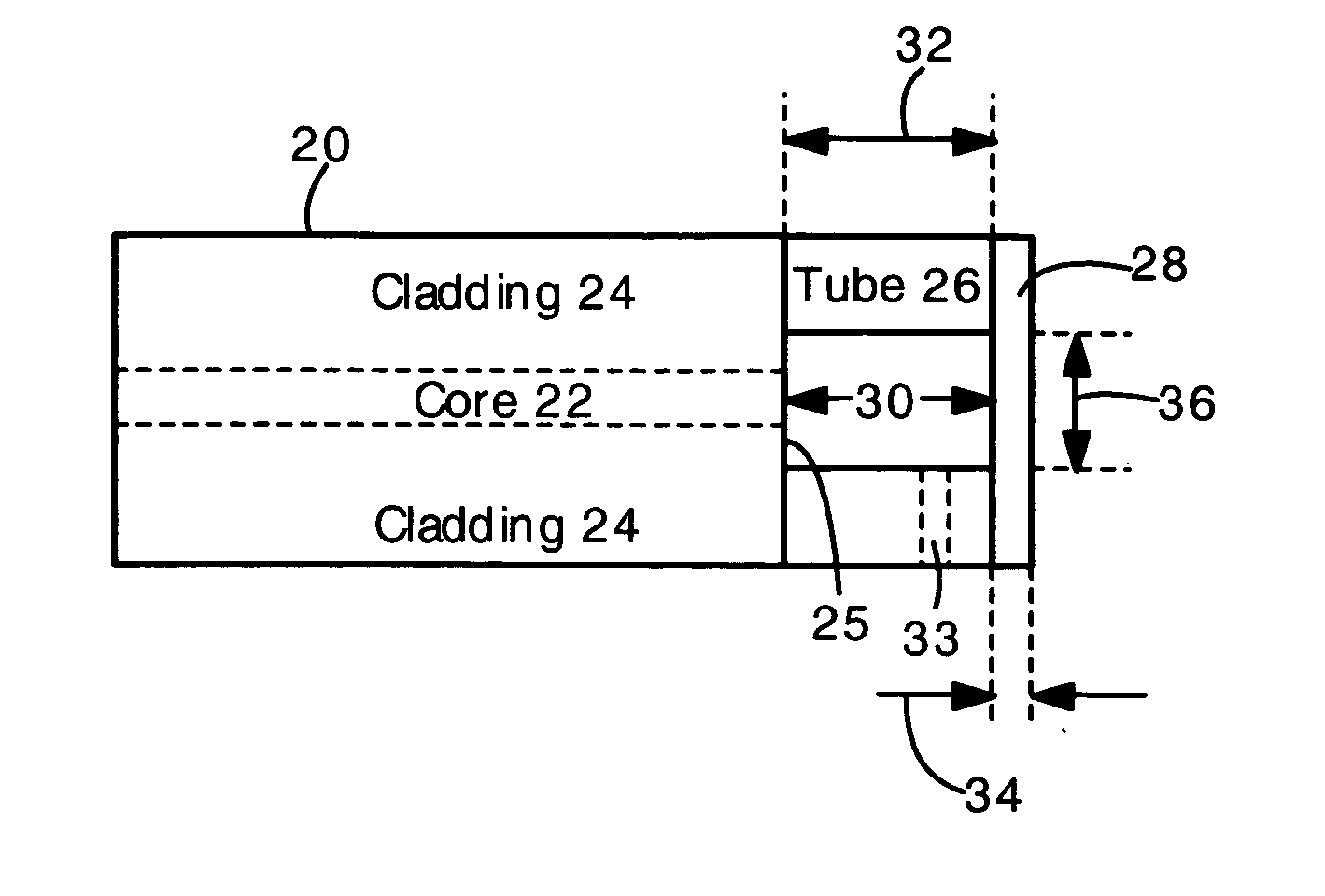
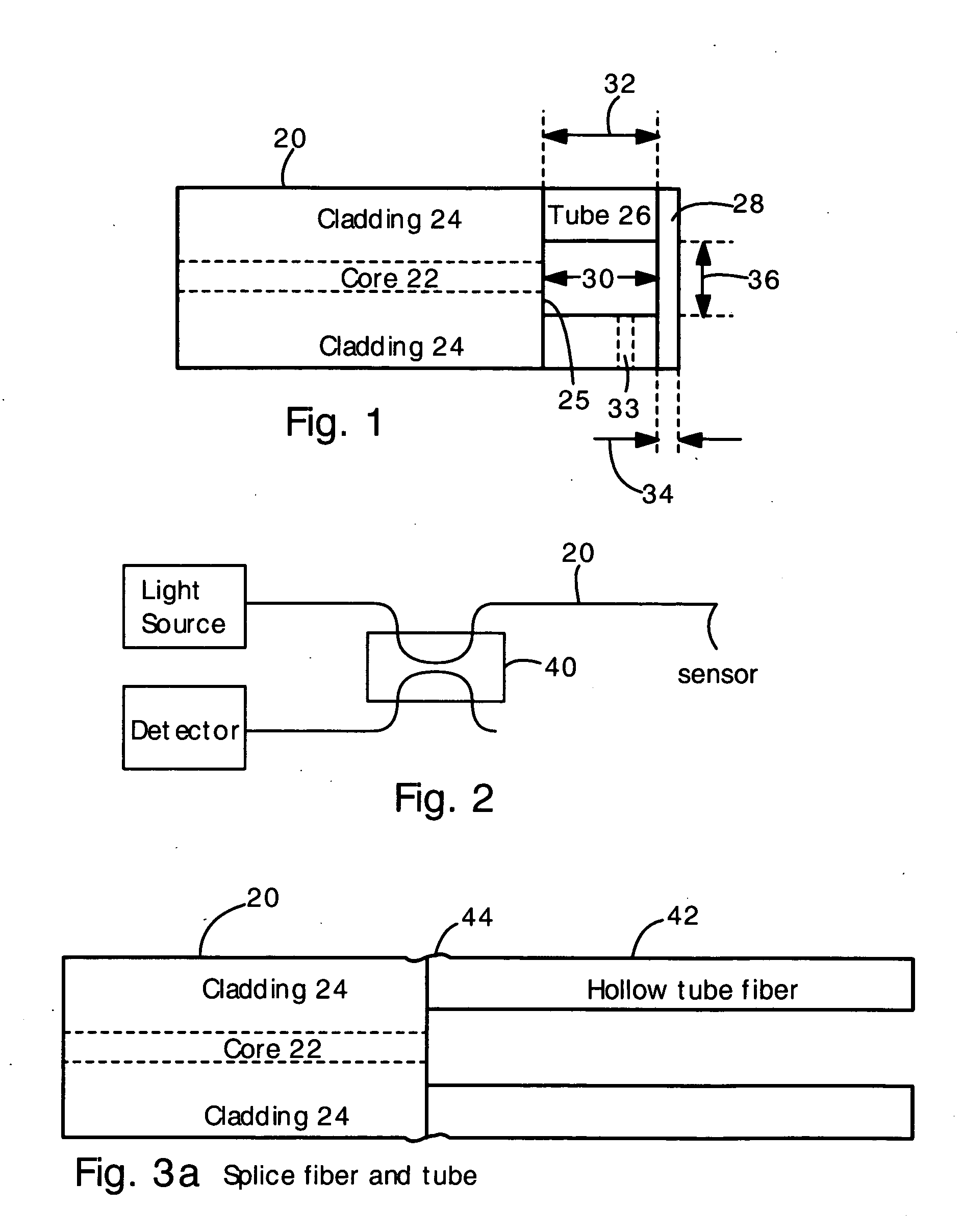
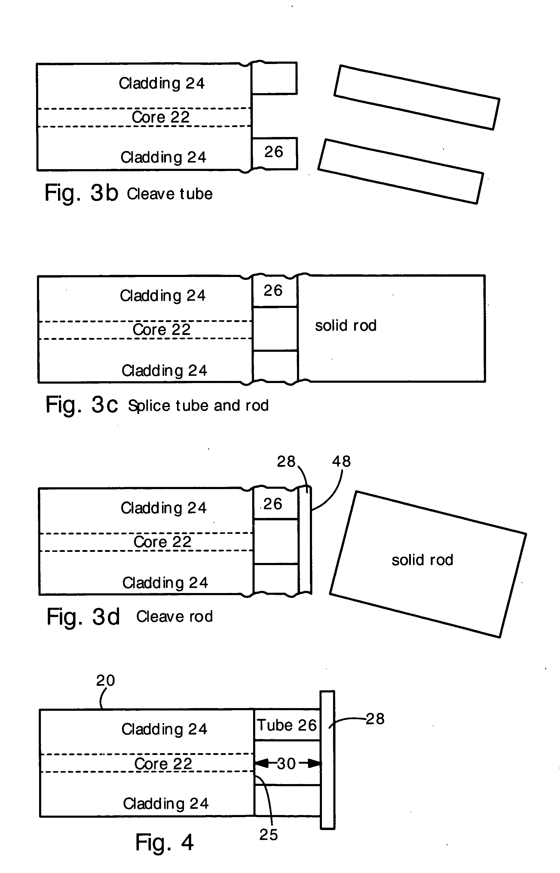
[0023] The present invention provides an optical fiber pressure sensor having a short length of hollow tube bonded to an endface of an optical fiber. A pressure-sensitive diaphragm is bonded to the opposite end of the hollow tube. The fiber endface and diaphragm define an etalon cavity. The diaphragm flexes in response to applied pressure, impact, vibrations or acoustic waves. The flexing diaphragm varies the etalon cavity length. The etalon cavity length is normally approximately equal to the length of the hollow tube. The fiber, hollow tube, and diaphragm are preferably made of the same material (e.g. fused silica or sapphire). The fiber, hollow tube, and diaphragm can all be bonded by fusion bonding at high temperature. The hollow tube can be formed by preferentially etching the core of a fiber. In an alternative embodiment, the fiber core is preferentially etched, and the diaphragm is bonded to the unetched cladding.

[0024]FIG. 1 shows a side view of an optical fiber pressure se...


PUM


Abstract

A fiber optic sensor has a hollow tube bonded to the endface of an optical fiber, and a diaphragm bonded to the hollow tube. The fiber endface and diaphragm comprise an etalon cavity. The length of the etalon cavity changes when applied pressure or acceleration flexes the diaphragm. The entire structure can be made of fused silica. The fiber, tube, and diaphragm can be bonded with a fusion splice. The present sensor is particularly well suited for measuring pressure or acceleration in high temperature, high pressure and corrosive environments (e.g., oil well downholes and jet engines). The present sensors are also suitable for use in biological and medical applications.

Description

CROSS-REFERENCE TO RELATED APPLICATIONS [0001] The present application claims the benefit of priority from co-pending provisional application 60 / 499,727, filed on Sep. 4, 2003.[0002] This invention was made under a grant from the Department of Energy (DOE contract number DE-FC36-01G011050). The U.S. government may have certain rights under any patent granted hereon.FIELD OF THE INVENTION [0003] The present invention relates generally to optical fiber pressure sensors and vibration and acceleration sensors. More particularly, the present invention relates to an optical fiber pressure sensor having an etalon cavity on an endface of an optical fiber. The pressure sensor is very small and capable of operation at high temperatures and in corrosive or chemically sensitive environments. BACKGROUND OF THE INVENTION [0004] Optical fiber pressure sensors are needed for measurement of pressure in extreme high temperature, high pressure and corrosive environments such as oil well downholes, jet...

Claims


Application Information

Patent Timeline
IPC IPC(8): G01BG01B9/02G01H9/00G01L9/00G01P15/093
CPCG01B9/02G01P15/093G01L9/0079G01H9/004G01B9/02023G01B2290/25
Inventor ZHU, YIZHENGWANG, XINGWEIXU, JUNCHENGWANG, ANBO
Owner VIRGINIA TECH INTPROP INC
Why Eureka
Try Eureka