Communication facilitation

a communication facilitation and object technology, applied in the field of unique object identification, can solve the problems of preventing successful detection and interpretation of bar codes, rfid tags, and affecting the appearance of product labels or packaging

Inactive Publication Date: 2005-03-24
SILVERBROOK RES PTY LTD
View PDF23 Cites 41 Cited by
  • Summary
  • Abstract
  • Description
  • Claims
  • Application Information

AI Technical Summary

Benefits of technology

In a ninth aspect the present invention provides a method of facilitating communications using a product item, the product item including an associated interface surface, the interface surface having disposed thereon or therein coded data indicative of an identity of the product item, the method including, in a sensing device: (a) sensing at least some of the coded data; (b) generating, using the sensed coded data, indicating data indicative of the product item identity; and, (c) transferring the indicating data to a computer system, the computer system being responsive to the indicating data to facilitate communications.
In a further aspect the present invention provides a method of creating a card for facilitating interaction between a user and a computer system, the method including, in a computer system: (a) receiving information indicative of an identity of the user; (b) generating at least one coded data portion indicative of the identity of the user; and, (c) disposing coded data on an interface surface of the card, the coded data including a plurality of the coded data portions disposed to thereby allow the identity of the user to be determined by sensing any one of the data portions with a sensing device.

Problems solved by technology

Additionally they often detract from the appearance of the product label or packaging.
Finally, damage to even a relatively minor portion of the bar code can prevent successful detection and interpretation of the bar code.
RFID tags have the advantage of supporting omnidirectional reading, but are comparatively expensive.
Additionally, the presence of metal or liquid can seriously interfere with RFID tag performance, undermining the omnidirectional reading advantage.
The read-only nature of most optical tags has been cited as a disadvantage, since status changes cannot be written to a tag as an item progresses through the supply chain.
However, this disadvantage is mitigated by the fact that a read-only tag can refer to information maintained dynamically on a network.
More broadly, the case studies do not clearly recognise benefits already beginning to accrue from systemic supply chain changes, such as better utilisation of UPC-based scan data collected at the point-of-sale, increasingly automated reordering and replenishment, and improving levels of communication and data sharing between different participants in the supply chain.
This in turn tends to overstate the benefits of these technologies.
However, a study by Alien Technology, the first manufacturer of RFID tags conforming to the Auto-ID Center's UHF RFID specifications, shows that cases of radiopaque product (such as soft drinks, shampoo, detergent, and coffee in metal containers) can only be effectively scanned when the case tags are within line-of-sight of tag readers as discussed in Alien Technology, “RFID Supply Chain Applications—Building Test 1”, February 2002.
Specifically, the case studies do not consider item-level RFID tagging in grocery to be cost-effective because of the high cost of RFID tags relative to the average item price.
Automatic scanning of a traditional UPC bar code, which only identifies item class, is problematic because multiple scans of the same item are difficult to avoid and impossible to detect from the bar code alone.
The unique EPC also prevents the checkout operator from multi-scanning a single item to account for a number of similar items, a common time-saving practice which can lead to inventory inaccuracy and thereby undermine automatic reordering and replenishment.
In reality, due to issues with radiopaque grocery items, an RFID-based automatic checkout is likely to require each item to pass through the RFID reader's field individually.
The grocery sector is also highly labour-intensive, with labour costs accounting for more than 50% of operating expenses.
Furthermore, the benefits of item-level tagging itself only accrue if such systemic changes actually take place.
However, the cost of apply RFID tags to provide item level tagging to further enhance loss reduction is currently cost prohibitive.
However, the 5 cent tag goal is still highly speculative, and even in multi-billion tag volumes there is currently no projected timeline for achieving an RFID tag price lower than 5 cents.
Since even wildly optimistic projected cost savings only marginally justify the cost of the most optimistically-priced RFID tags, it is unlikely that universal item-level RFID tagging in the grocery sector is justified in the foreseeable future.
In addition to this however, other disadvantages of the RFID tagging scheme, such as the difficulty of scanning in the presence of radiopaque products, and issues surrounding privacy, make the use of RFID tags undesirable in item-level tagging of more expensive products even where the RFID cost becomes negligible.

Method used


Image

  • Communication facilitation
  • Communication facilitation
  • Communication facilitation

Examples


first embodiment

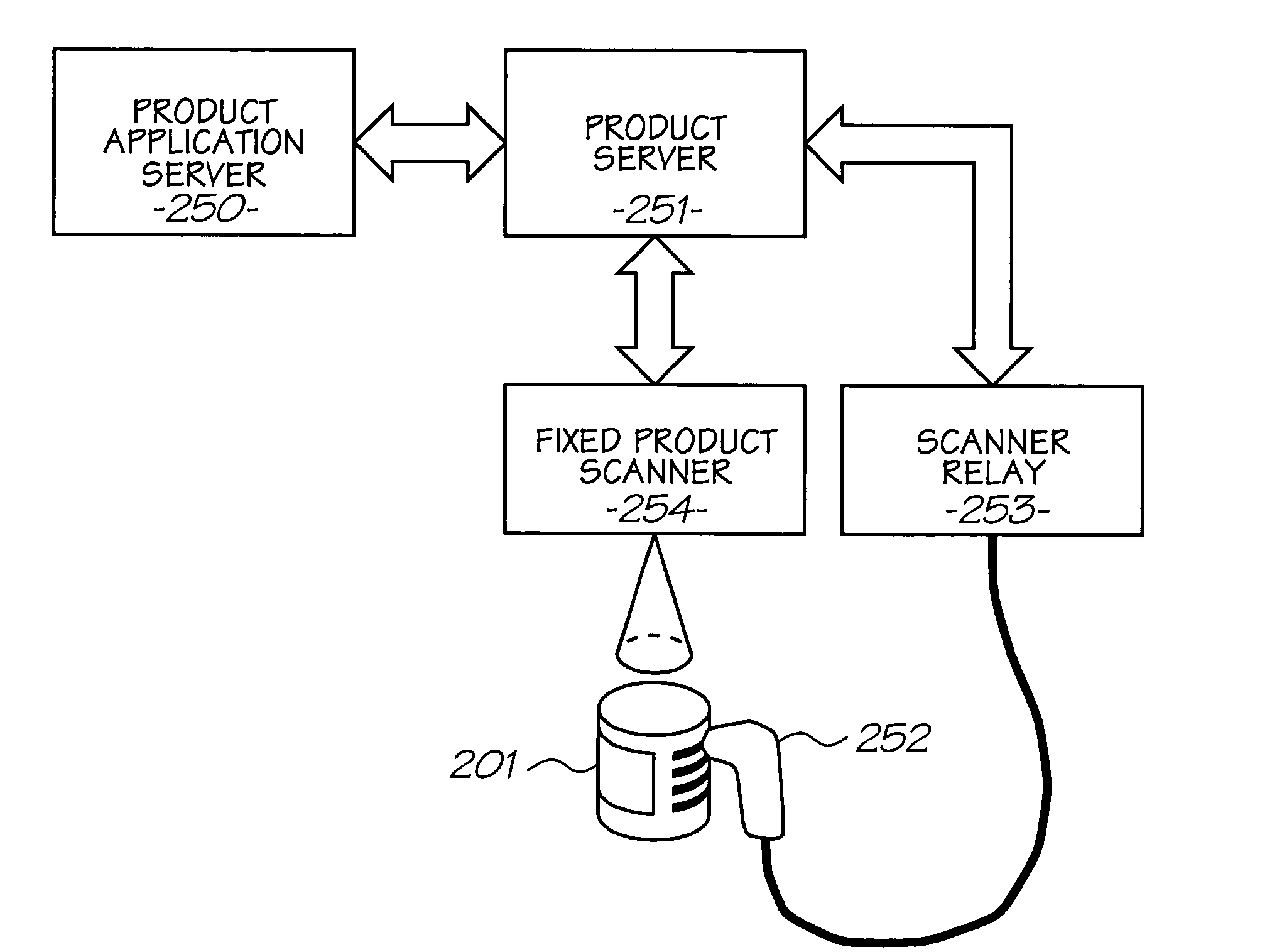
FIG. 58, FIG. 59, FIG. 60 and FIG. 61 show a Hyperlabel™ scanner 4000. The scanner is designed to image and decode Hyperlabel™ tags when its tip 4003 is brought into close proximity or contact with a Hyperlabel™ tagged surface. The scanner can be operated in free mode, in which it continuously and automatically scans tags within its field of view; or in triggered mode, in which it only scans tags when its trigger 4008 is held depressed. Although the scanner is designed with a limited depth of field, thus reducing the likelihood of unintentional scans in free mode, triggered mode can be used to avoid unintentional scans. The trigger may also be configured to be manually operated (as shown), or configured to be automatically activated when the scanner makes contact with the surface. Because an individual product item is tagged with a unique item ID, there is no possibility of duplicate scans.

During normal operation the scanner returns the item ID encoded in a Hyperlabel™ tag, but ign...

second embodiment

FIGS. 72, 73 and 74 show a Hyperlabel™ scanner 4000. FIGS. 72 and 73 use similar reference numerals to FIGS. 58 and 59 to denote similar elements. In this example, the optical assembly shown in FIG. 59 is replaced with a laser based scanning system, an example of which is shown in FIG. 74.

As shown in FIG. 74, a scan beam 4540 is produced by a laser 4502. The laser produces a narrowband near-infrared beam matched to the peak wavelength of the near-infrared ink used to print the Hyperlabel™ tags. An optional amplitude modulator 4503 allows the amplitude of the beam to be modulated, e.g. for ambient light suppression or ranging purposes as discussed below. An optional beam expander 4504 allows the beam to be reduced to produce the desired spot size. The laser is typically a solid-state laser.

A pair of mirrors 4506 and 4507 injects the scan beam into line with the retroreflective collection system, as described further below.

An optional focussing lens 4508 focusses the beam prior t...


PUM

PropertyMeasurementUnit
shrinkage rateaaaaaaaaaa
shrinkageaaaaaaaaaa

Abstract

A method of facilitating communications using a product item, the product item including an associated interface surface, the interface surface having disposed thereon or therein coded data indicative of an identity of the product item, the method including, in a sensing device: (a) sensing at least some of the coded data; (b) generating, using the sensed coded data, indicating data indicative of the product item identity; and, (c) transferring the indicating data to a computer system, the computer system being responsive to the indicating data to facilitate communications.

Description

FIELD OF INVENTION This invention relates to unique object identification and, in particular, to methods and systems for identifying and interacting with objects. BACKGROUND The reference to any prior art in this specification is not, and should not be taken as, an acknowledgement or any form of suggestion that the prior art forms part of the common general knowledge. For the purposes of automatic identification, a product item is commonly identified by a 12-digit Universal Product Code (UPC), encoded machine-readably in the form of a printed bar code. The most common UPC numbering system incorporates a 5-digit manufacturer number and a 5-digit item number. Because of its limited precision, a UPC is used to identify a class of product rather than an individual product item. The Uniform Code Council and EAN International define and administer the UPC and related codes as subsets of the 14-digit Global Trade Item Number (GTIN). Within supply chain management, there is considerable...

Claims


Application Information

Patent Timeline
Patent Type & Authority Applications(United States)
IPC IPC(8): B41J2/01C09B49/12C09B57/10C09D11/00C09D11/02D21H19/38G01N33/48G01N33/50G05B15/00G06F3/08G06F7/00G06F7/02G06F7/08G06F15/00G06F17/00G06F17/30G06K5/00G06K7/00G06K7/10G06K7/14G06K9/00G06K9/18G06K9/20G06K9/22G06K9/78G06K15/00G06K19/06G06Q10/00G06Q10/08G06Q20/20G06Q30/02G06Q30/06H04N1/04
CPCG06F3/014H04N5/378G06K7/10554G06K7/10623G06K7/10693G06K7/10722G06K7/10772G06Q10/00G06Q10/087G06Q20/20G06Q30/02G06Q30/0207G06Q30/0212G06Q30/0217G06Q30/0236G06Q30/0259G06Q30/0267G06Q30/0601H04N3/1568H04N5/33H04N5/3559H04N5/3651H04N5/3742H04N5/37457H04N5/3765G06F3/0317G06F3/0321H04N25/59H04N25/671H04N25/767H04N25/778H04N25/745H04N25/75
Inventor SILVERBROOK, KIALAPSTUN, PAUL
Owner SILVERBROOK RES PTY LTD
Why Eureka
Try Eureka