

Apparatus controlling write current supplied to head and method for the apparatus
a technology of write current and apparatus, which is applied in the direction of digital recording, special recording techniques, instruments, etc., can solve the problems of increasing power consumption, affecting the flow of write current (effective current), and increasing the frequency of the supply and consumption of boosted power voltages to the head i
- Summary
- Abstract
- Description
- Claims
- Application Information
AI Technical Summary
Problems solved by technology
Method used
Image

Examples
first embodiment
[First Embodiment]
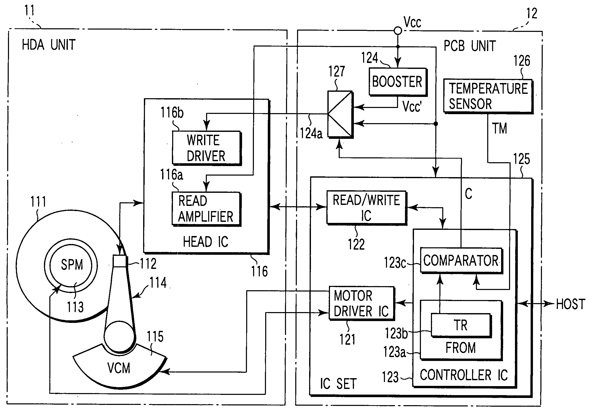
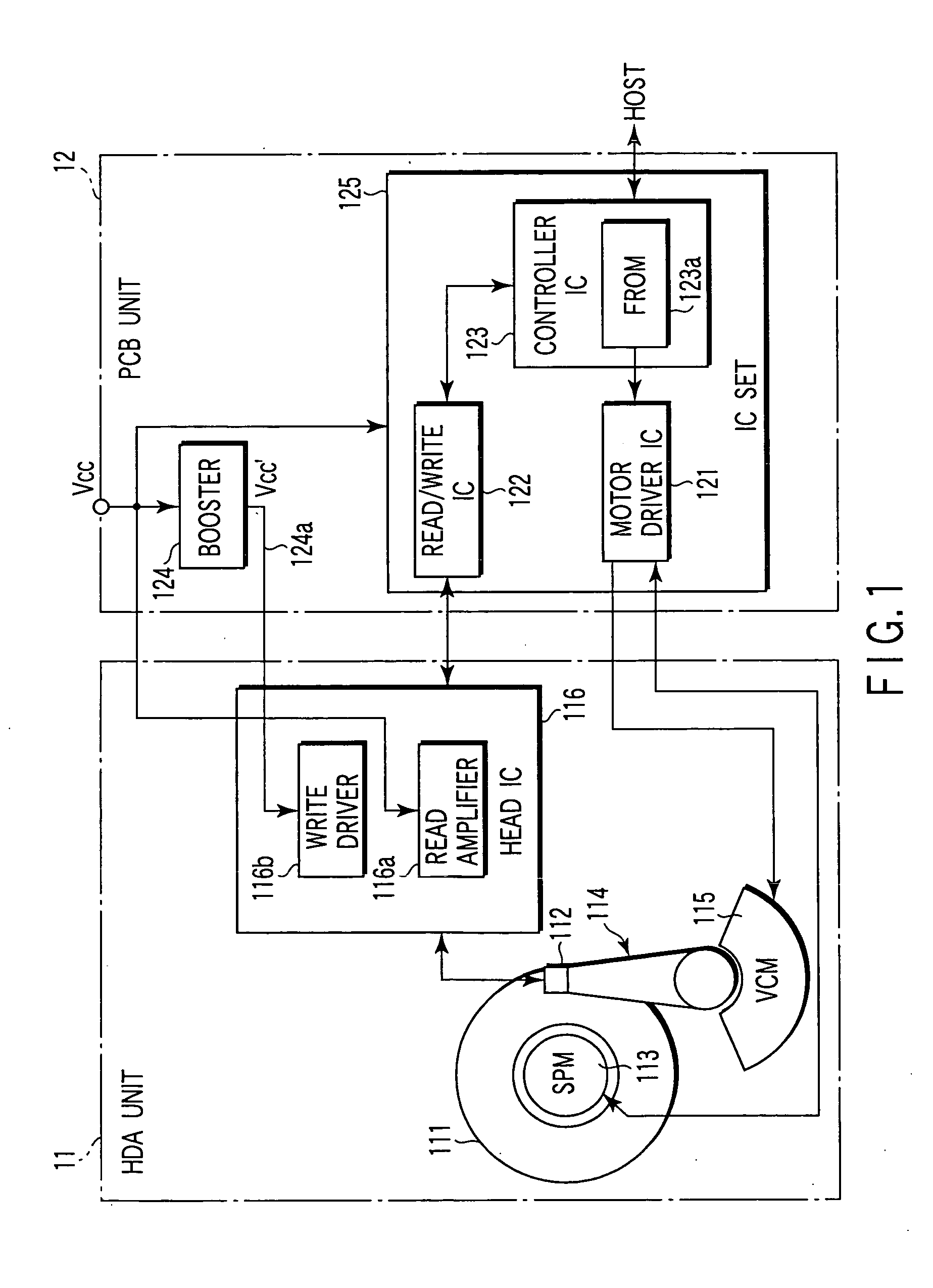
FIG. 1 is a block diagram showing the configuration of a hard disk drive according to a first embodiment of the present invention. The hard disk drive (HDD) in FIG. 1 is roughly composed of a head disk assembly unit (hereinafter referred to as an HDA unit) 11 and a printed circuit board unit (hereinafter referred to as a PCB unit) 12.
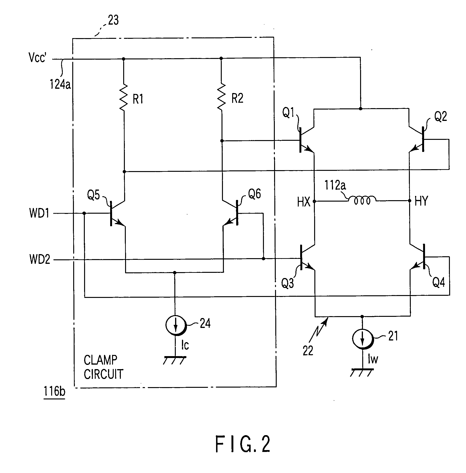
The HDA unit 11 includes a disk (magnetic disk) 111, a head (magnetic head) 112, a spindle motor (SPM) 113, an actuator 114, a voice coil motor (VCM) 115, and a head IC 116. The disk 111 has two disk surfaces, a top surface and a bottom surface. At least one of the two disk surfaces of the disk 111 constitutes a recording surface on which data is magnetically recorded. The head 112 is placed in association with one of the disk surfaces of the disk 111. The head 112 is a composite head composed of, for example, a magneto-resistive (MR) element (not shown) and an inductive thin-film element 112a (see FIG. 2). The MR element is used as ...
second embodiment
[Second Embodiment]
Now, a second embodiment of the present invention will be described. FIG. 7 shows the relationship between the write current (I) and overwrite characteristics (OWM) 81 and 82. The overwrite characteristic 81 relates to the write current at room temperature (25° C.). This figure indicates that the overwrite characteristic 81 is improved with increasing write current. The figure also indicates that the overwrite characteristic 81 is saturated at a certain write current value and is then no longer improved even with a further increase in the write current. In the example shown in FIG. 7, the overwrite characteristic is saturated with a write current of about 40 mA. On the other hand, the overwrite characteristic 82 relates to the write current at low temperature (0° C.). This figure indicates that a larger current is required to saturate the overwrite characteristic 82, compared to the overwrite characteristic 81 at room temperature. In the example shown in FIG. 7, ...
third embodiment
[Third Embodiment]
Now, a third embodiment of the present invention will be described. As previously described, the transient response speed of the write current varies depending on the value of the write current. Further, for the HDD, the write current is preferably varied depending on the environmental temperature. At low temperature, the write current needs to be large. Then, in the third embodiment, the value of the write current, determined from the environmental temperature measured by the temperature sensor 126, is used to switch the power voltage applied to the write driver 116b. In this point, the third embodiment is different from the second embodiment, which uses the result of temperature measurement made by the temperature sensor 126 to switch the power voltage.
FIG. 9 is a block diagram showing the configuration of an HDD according to the third embodiment of the present invention. Components of the third embodiment similar to those in FIG. 8 are denoted by the same refe...
PUM
 Abstract
Description
Claims
Application Information