Fusion splicing of highly rare-earth-doped optical fibers

a technology of optical fibers and fusion splicing, which is applied in the field of communication systems, can solve the problems of high splice loss of hred fibers, high splice loss when spliced with dissimilar fibers, and deter the use of hred fibers, and achieve the effects of accurate determination, low splice loss, and high splice loss

Inactive Publication Date: 2005-03-24
TELEFON AB LM ERICSSON (PUBL)
View PDF10 Cites 8 Cited by
  • Summary
  • Abstract
  • Description
  • Claims
  • Application Information

AI Technical Summary

Benefits of technology

The present invention provides a method and arrangement for achieving low splice-losses when connecting Highly Rare-Earth-Doped (HRED) optical fibers and dissimilar optical fibers having a large Mode Field Diameter (MFD) mismatch. Warm images are taken during a pre-fusion process. Thermal light emissions from both the air-discharge and the fiber are analyzed, and an arc-center position is determined. By taking into account the light propagation direction and the degree of MFD-mismatch, the end-surfaces of the HRED fiber and the dissimilar fiber are intentionally positioned with a relatively large longitudinal offset with respect to the arc-center. The abutted portions of the two fibers are then asymmetrically heated with different fusion temperatures dur

Problems solved by technology

The major deterrent to the use of HRED fibers is high splice loss when spliced with dissimilar fibers.
A primary reason causing high splice losses for HRED fibers is the initial MFD-mismatch.
The Applicant's studies have found that the previous methods using TEC techniques may work effectively for fibers without rare-earth dopants and/or with low concentration of dopants, but they are not effective for HRED fibers.
It was discovered that, for the HRED fibers, besides the problem of initial MFD-mismatch, the major cause of high splice losses can be attributed to fast diffusion of core dopants occurring in the fusion processes.
Thus, instead of achieving the MFD-match, the additional heat treatment used in the previous methods may lead to an inverted MFD-mismatch (i.e., the HRED fiber that ordinarily has a smaller MFD gets an effective MFD that is much larger than that of the connected fiber).
Thus, in the case of light injection from the HRED fiber, the cladding modes are easily excited, and splice losses as

Method used


Image

  • Fusion splicing of highly rare-earth-doped optical fibers
  • Fusion splicing of highly rare-earth-doped optical fibers
  • Fusion splicing of highly rare-earth-doped optical fibers

Examples


case 1

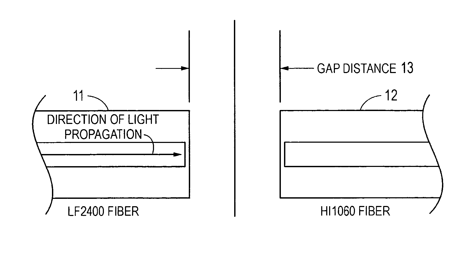
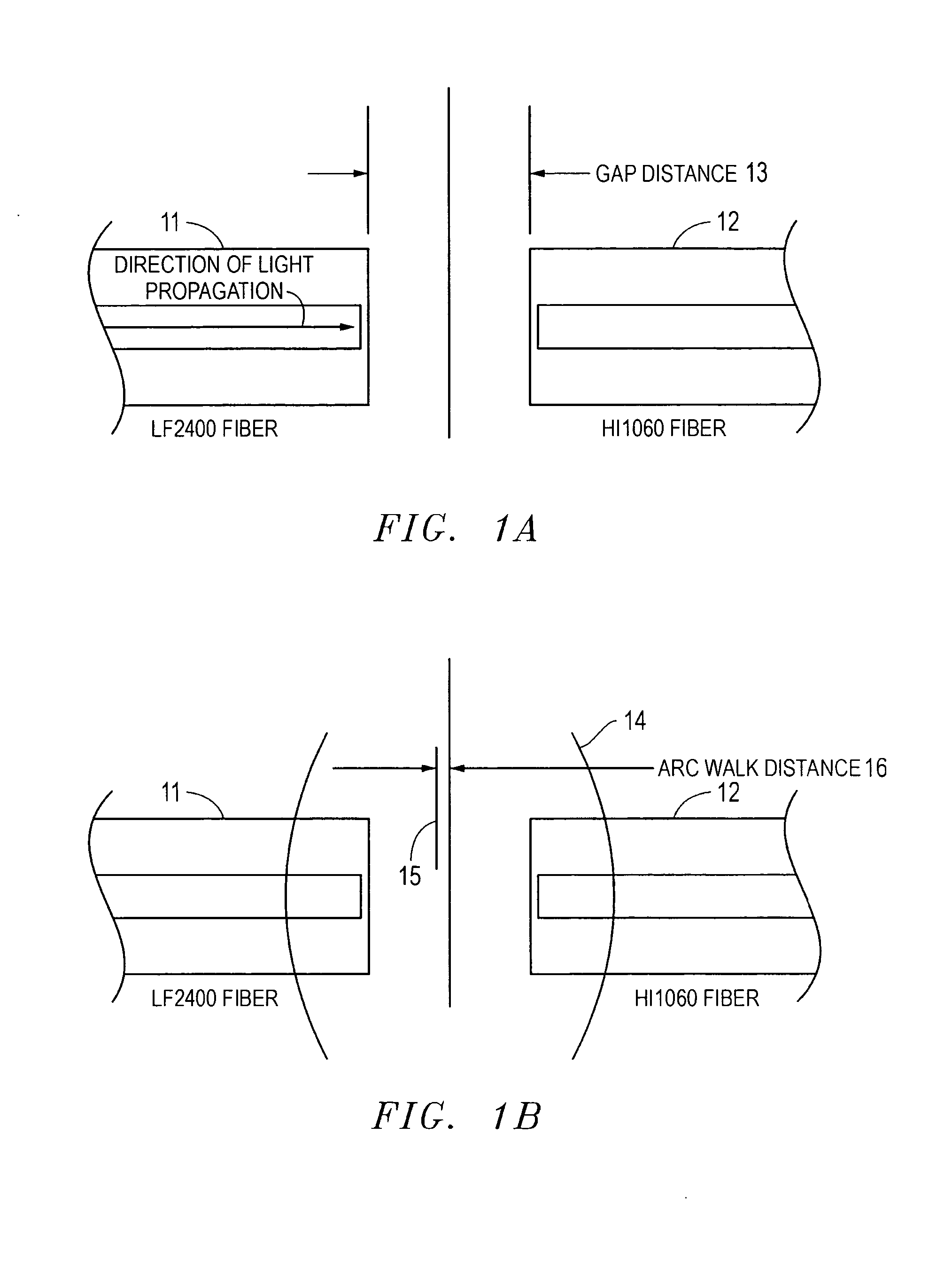
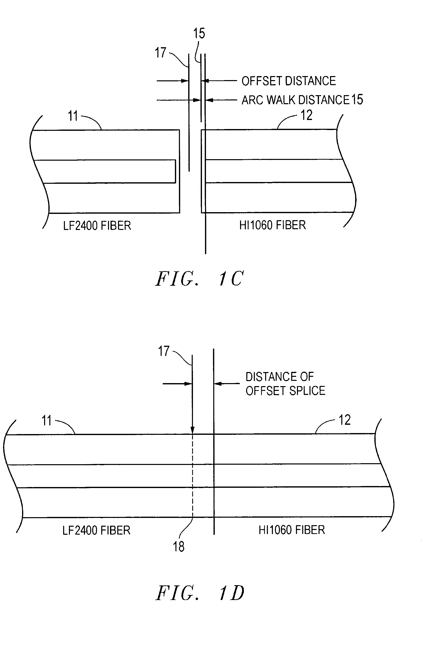
ght is injected from the HRED fiber, and the initial MFD-mismatch of the two fibers is relatively small. A typical example is the fiber combination between Liekki LF2400™ (an HRED fiber with a peak absorption of approximately 40 dB / m and a corresponding MFD of approximately 6 μm @1550 nm) and Corning PureMode™ HI1060 (an NRED fiber with an MFD of approximately 8.5 μm @1550 nm). This combination provides an initial MFD-mismatch of approximately 2.5 μm.

case 2

ght is injected from the NRED fiber, and the initial MFD-mismatch of the two fibers is relatively small. A typical example is the same fiber combination described for Case 1.

case 3

ght is injected from the HRED fiber, and the initial MFD-mismatch of the two fibers is relatively large. A typical example is the fiber combination between Liekki LF2400™ and Corning SMF28™ (an NRED fiber with an MFD of approximately 10.5 μm @1550nm). This combination provides an initial MFD-mismatch of approximately 4.5 μm.


PUM


Abstract

A method and arrangement for achieving low splice-losses when connecting Highly Rare-Earth-Doped (HRED) optical fibers and dissimilar optical fibers having a large Mode Field Diameter (MFD) mismatch. Warm images are taken during a pre-fusion process to capture thermal light emissions and determine an arc-center position. The end-surfaces of the fibers are abutted and longitudinally offset from the arc-center, based on the light propagation direction and the MFD-mismatch. The fibers are then asymmetrically heated with different fusion temperatures during the main fusion processes. An MFD-match is achieved with well-defined fusion currents and fusion time. To maintain the same offset distance in a sequence of splices, the main-fusion arc-center position is determined by a process of direct arc-recentering. Variations of fusion temperature caused by changes of electrode conditions and the operating environment are monitored in real-time, and an arc-check process is invoked to compensate for the large variations of fusion temperature.

Description

BACKGROUND The present invention relates to communication systems. More particularly, and not by way of limitation, the present invention is directed to a method and arrangement for splicing Highly Rare-Earth-Doped (HRED) optical fibers and dissimilar optical fibers having a large Mode Field Diameter (MFD) mismatch. In recent years, greater numbers of HRED fibers have been developed for special applications in optical communication systems. Examples include Erbium-Doped Fiber Amplifiers (EDFA), Amplified Spontaneous Emission (ASE) light sources, fiber lasers, and the like. HRED fibers are very attractive due mainly to the excellent performance achieved by a very short length of fiber. For example, by using highly Erbium-Doped Fibers (EDFs) characterized by the peak absorption of 40 dB / m at operating wavelengths, it is possible to reduce the required length of fiber by a factor of 5-10 to get the same performance achieved by traditional optical fibers. EDFs have high power density ...

Claims


Application Information

Patent Timeline
IPC IPC(8): G01K11/06G02B6/255
CPCG02B6/2551G01K11/06
Inventor HUANG, WEI-PING
Owner TELEFON AB LM ERICSSON (PUBL)
Why Eureka
Try Eureka