
Method and apparatus for forming low optical loss splices

a technology of optical fiber and splicing method, which is applied in the direction of glass making apparatus, manufacturing tools, instruments, etc., can solve the problems of inacceptable splicing loss, achieve the effect of avoiding the inconvenience of handling and mixing gases, maintaining a precise tension of the fiber, and reducing the temperature profil

Inactive Publication Date: 2004-08-26
VYTRAN
View PDF32 Cites 1 Cited by
  • Summary
  • Abstract
  • Description
  • Claims
  • Application Information

AI Technical Summary

Benefits of technology

[0013] It has been found that organic liquids, particularly alcohols, more particularly, alcohols having six or fewer carbon atoms and only one hydroxyl group, and optimally, methanol, provide flames having an ideal temperature profile for adiabatic mode-field expansion of specialty fibers, particularly, for adiabatic expansion of dispersion compensating fibers. Such flames provide a lower temperature profile than typical oxygen / hydrogen or oxygen / hydrocarbon-gas fueled flames and thus provide a more gradual, adiabatic expansion than can be obtained with other heat sources. Furthermore, since a liquid fuel is used, the inconvenience of handling and mixing gases is avoided.

Problems solved by technology

Unfortunately, however, specialty fibers and the fibers or devices to which they will be spliced, usually have significantly mismatched mode-field diameters resulting in unacceptable splice loss.

Method used


Image

  • Method and apparatus for forming low optical loss splices
  • Method and apparatus for forming low optical loss splices
  • Method and apparatus for forming low optical loss splices

Examples


Embodiment Construction

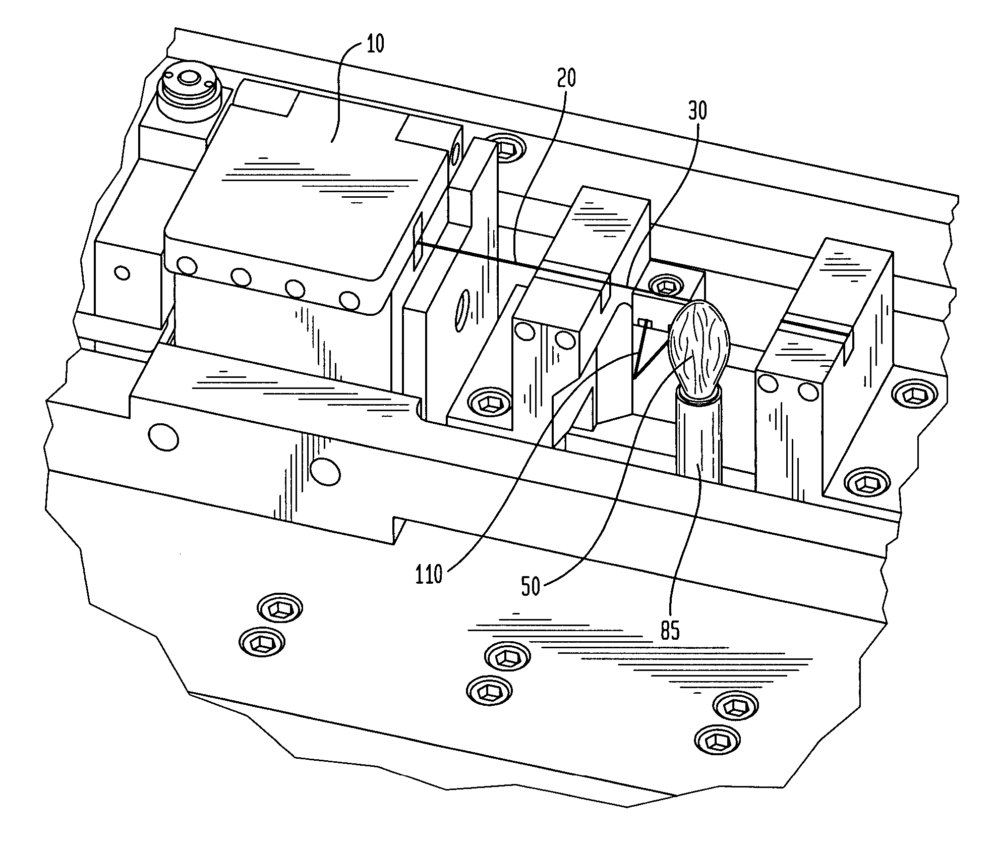
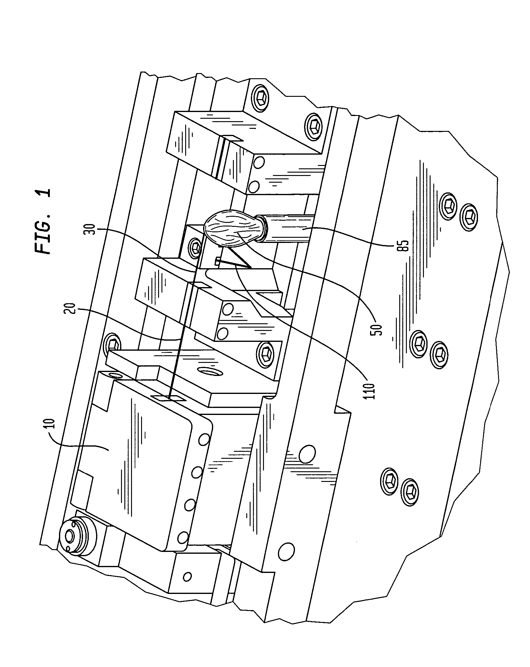
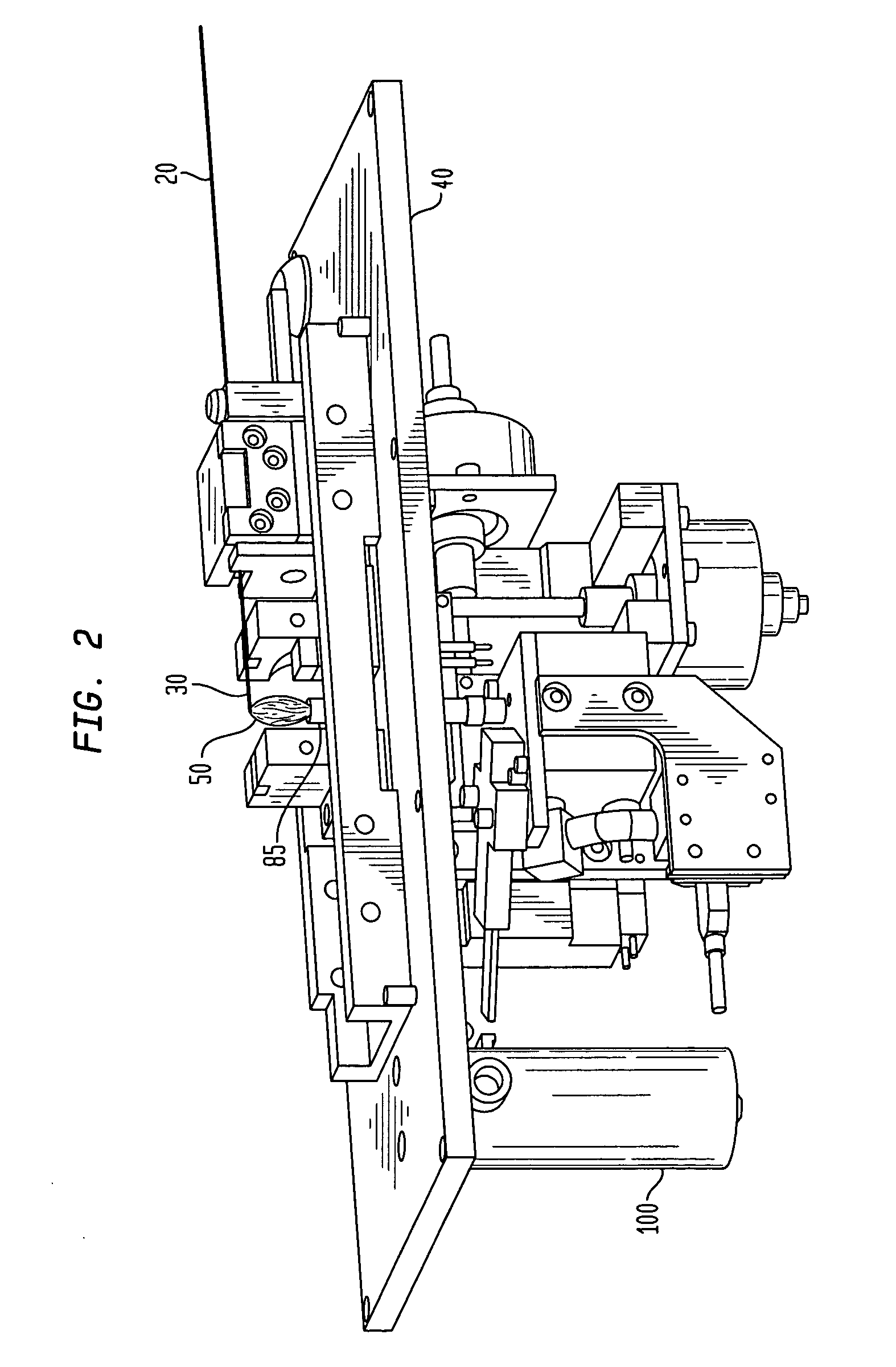
[0018] According to one embodiment of the invention, optical fibers of differing mode-field diameters are connected in a splice of low optical loss as follows. First, the optical fiber having the smaller mode-field diameter is stripped and cleaved according to well-known methods. The next step is to expose the cleaved end to a heat source for about 1 minute to about 40 minutes, more preferably, from about 10 minutes to about 30 minutes. Preferably, the heat source provides a temperature profile of from about 500.degree. C. to about 2000.degree. C. at the region where the optical fiber end is positioned, more preferably, of from about 1000.degree. C. to about 1500.degree. C., still more preferably, of from about 1100.degree. C. to about 1200.degree. C., and optimally about 1150.degree. C.

[0019] The heat source can be any heat source, for example, an electric furnace or a flame produced by burning an organic solid or liquid, such as an alcohol. In one embodiment of the invention, the ...


PUM

PropertyMeasurementUnit
Lengthaaaaaaaaaa
Lengthaaaaaaaaaa
Angleaaaaaaaaaa

Abstract

The invention is directed to methods for adiabatically expanding the mode-field diameter of an optical fiber by heating the end of the optical fiber. The fiber's end is heated by a heat source, preferably, a flame fueled by an organic liquid. Preferably, the organic-liquid fuel is an alcohol, more preferably, an alcohol having six or fewer carbon atoms and only one hydroxyl group, and optimally methanol.

Description

[0001] This application claims the benefit of U.S. Provisional Application No. 60 / 427,893 filed Nov. 20, 2002, entitled Method and Apparatus for Forming Low-Loss Splices Between Transmission Optical Fibers and Specialty Optical Fibers, by E. Mies et al., which application is hereby incorporated herein by reference.1. FIELD[0002] This invention relates to methods of splicing optical fibers with low optical loss and, in particular, to methods for splicing transmission fibers to specialty fibers.2. BACKGROUND[0003] Optical fibers are key components in modern telecommunication systems. An optical fiber is a thin strand of glass, capable of transmitting optical signals over long distances with very low loss. In its simplest form, an optical fiber is a cylindrical wave guide comprising a small-diameter silica core having a first index of refraction surrounded by a silica cladding having a second (lower) index of refraction. A polymeric coating surrounding the cladding protects the fiber. ...

Claims


Application Information

Patent Timeline
IPC IPC(8): G02B6/14G02B6/255
CPCG02B6/02004G02B6/2552G02B6/14G02B6/02261
Inventor MICS, ERICVENKATARAMAN, LATHA
Owner VYTRAN
Learn More