Imprint lithography templates having alignment marks

a technology of alignment marks and lithography templates, which is applied in the field of imprint lithography, can solve the problems of inability to mass produce sub-50 nm lithography at low cost, economic impracticality of using sub-50 nm structures to mass produce, and limited lithography resolution for this type of lithography

Inactive Publication Date: 2005-03-24
BOARD OF RGT THE UNIV OF TEXAS SYST
View PDF99 Cites 141 Cited by
  • Summary
  • Abstract
  • Description
  • Claims
  • Application Information

AI Technical Summary

Benefits of technology

[0015] One or more embodiments of the present invention satisfy one or more of the above-identified needs in the art. In particular, one embodiment of the present invention is an imprint template for imprint lithography that comprises alignment marks embedded in bulk material of the imprint template.

Problems solved by technology

The lithography resolution for this type of lithography is typically limited by a wavelength of the beam constituents, scattering in the resist and the substrate, and properties of the resist.
Several lithography technologies have been developed to satisfy this need, but they all suffer drawbacks, and none of them can mass produce sub-50 nm lithography at low cost.
For example, although electron beam lithography has demonstrated a 10 nm lithography resolution, using it for mass production of sub 50 nm structures seems economically impractical due to inherent low throughput in serial electron beam lithography tools.
However, X-ray lithography tools are rather expensive, and their ability for mass producing sub-50 nm structures is yet to be seen.
However, the practicality of such lithography technologies as a manufacturing tool is hard to judge at this point.
First, PMMA does not adhere well to the SiO2 mold due to its hydrophilic surface, and good mold or imprint template release properties are important for fabricating nanoscale features.
Second, PMMA shrinkage is less than 0.5% for large changes of temperature and pressure.
This is problematic since such alignment marks are typically formed of the same material as that of the mold or imprint template itself.
As such, since the index of refraction of the mold or imprint template is substantially the same as that of a thin film used to transfer the imprint pattern (at least to manufacturing tolerances), an ability to resolve alignment marks in the mold or imprint template is severely hindered.

Method used


Image

  • Imprint lithography templates having alignment marks
  • Imprint lithography templates having alignment marks
  • Imprint lithography templates having alignment marks

Examples


Embodiment Construction

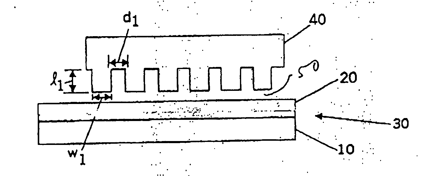
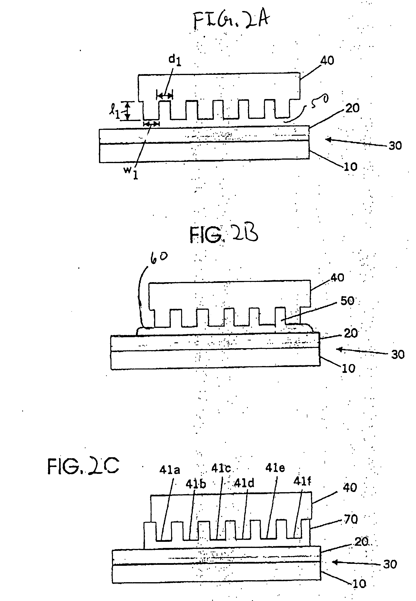
[0020] One or more embodiments of the present invention relate to an imprint template or mold for imprint lithography that comprises alignment marks embedded in bulk material of the imprint template. In addition, in accordance with one or more further embodiments of the present invention that are useful for optical alignment techniques, the alignment marks are fabricated from a material whose index of refraction is different from that of at least the bulk material of the imprint template surrounding the alignment marks. Still further, in accordance with one or more further embodiments of the present invention, the alignment marks are fabricated from a material whose index of refraction is different from that of at least the bulk material of the imprint template surrounding the alignment marks and that of the material into which an imprint is made in carrying out an imprint lithography process. Advantageously, in accordance with such embodiments, differences in indices of refraction ...


PUM

PropertyMeasurementUnit
feature sizesaaaaaaaaaa
shrinkageaaaaaaaaaa
aspect ratioaaaaaaaaaa

Abstract

One embodiment of the present invention is an imprint template for imprint lithography that comprises alignment marks embedded in bulk material of the imprint template.

Description

BACKGROUND OF THE INVENTION [0001] One or more embodiments of the present invention relate generally to imprint lithography. In particular, one or more embodiments of the present invention relate to imprint lithography templates having alignment marks. [0002] There is currently a strong trend toward micro-fabrication, i.e., fabricating small structures and downsizing existing structures. For example, micro-fabrication typically involves fabricating structures having features on the order of micro-meters or smaller. One area in which micro-fabrication has had a sizeable impact is in microelectronics. In particular, downsizing of microelectronic structures has generally allowed such microelectronic structures to be less expensive, have higher performance, exhibit reduced power consumption, and contain more components for a given dimension relative to conventional electronic devices. Although micro-fabrication has been utilized widely in the electronics industry, it has also been utili...

Claims


Application Information

Patent Timeline
Patent Type & Authority Applications(United States)
IPC IPC(8): G03FG03F7/00G03F9/00
CPCB82Y10/00G03F9/00G03F7/0002B82Y40/00G03F9/7073
Inventor BAILEY, TODD C.JOHNSON, STEPHEN C.COLBURN, MATTHEW E.CHOI, BYUNG-JINSMITH, BRITAIN J.EKERDT, JOHN G.WILLSON, CARLTON G.SREENIVASAN, SIDLGATA V.
Owner BOARD OF RGT THE UNIV OF TEXAS SYST
Why Eureka
Try Eureka