Cylindrical grinder, and mechanism for producing relative movement between grinding wheel and workpiece in cylindrical grinder

a cylindrical grinder and relative movement technology, applied in the field of cylindrical grinders, can solve the problems of easy grinding burn, increased wheel head size, interference with workpieces or workpiece support sections, etc., and achieves accurate displacement, high speed, and easy control of the movement distance of the drive block.

Inactive Publication Date: 2005-03-24
TOYODA MASCH WORKS LTD
View PDF7 Cites 14 Cited by
  • Summary
  • Abstract
  • Description
  • Claims
  • Application Information

AI Technical Summary

Benefits of technology

[0010] In view of the foregoing, an object of the present invention is to provide a cylindrical grinder which can grind opposite end surfaces of a workpiece without inverting the workpiece and which can employ a grinding wheel of reduced diameter.
[0011] Another object of the present invention is to provide a parallel link mechanism for a cylindrical grinder which can displace a movable body, such as a grinding wheel, at high speed and with high accuracy.
[0012] According to a first aspect of the present invention, there is provided a cylindrical grinder which comprises a workpiece support section adapted to support a generally cylindrical workpiece and rotate the workpiece about a rotational axis, and a wheel head adapted to support and rotate a grinding wheel. The wheel head is moved relative to the workpiece support section, along a first direction parallel to the rotational axis of the workpiece and along a second direction perpendicular to the first direction in order to grind an outer surface of the workpiece. The wheel head is turnable relative to the workpiece so that a rotational axis of the grinding wheel can be tilted within a plane substantially passing through the rotational axis of the grinding wheel and the rotational axis of the workpiece, within a range extending across a reference plane perpendicular to the rotational axis of the workpiece.

Problems solved by technology

In such a grinder, grinding burn is prone to occur when an end surface of the grinding wheel T comes into contact with an end surface of the workpiece W over a wide area.
However, in this case, since a grinding wheel is provided on each of the opposite sides of the wheel head, the size of the wheel head increases, and the grinding wheel that is not used for on-going grinding may interfere with the workpiece or the workpiece support section.
Therefore, when a grinding wheel is provided on each of the opposite sides of the wheel head, limitations are imposed on shapes of workpieces which can be ground, thereby impairing the versatility of the cylindrical grinder.

Method used


Image

  • Cylindrical grinder, and mechanism for producing relative movement between grinding wheel and workpiece in cylindrical grinder
  • Cylindrical grinder, and mechanism for producing relative movement between grinding wheel and workpiece in cylindrical grinder
  • Cylindrical grinder, and mechanism for producing relative movement between grinding wheel and workpiece in cylindrical grinder

Examples


first embodiment

[0055] A cylindrical grinder according to a first embodiment of the invention will be described with reference to the drawings.

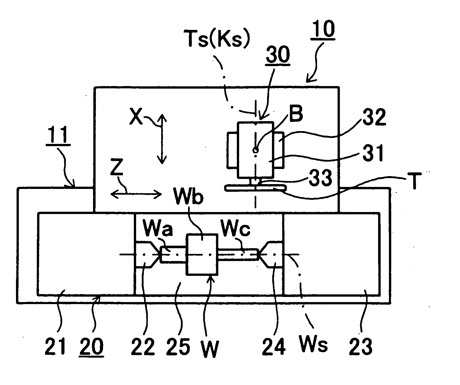
[0056] As shown in FIG. 3, a cylindrical grinder 10 according to the present embodiment includes a bed 11, serving as a base; a workpiece support section 20 disposed on a front portion of the bed 11 and supporting a workpiece W in such a manner that the workpiece W extends along the left-right direction; and a wheel head section 30 disposed on a rear portion of the bed 11 and having a wheel head 31 to which a disc-shaped grinding wheel T is attached. The workpiece support section 20 includes a table 25 disposed on the top surface of the bed 11 to be slidable along the Z-axis direction; a spindle head 21 fixedly disposed on the top surface of the table 25; and a tailstock 23 disposed on the top surface of the table 25 to be slidable along the Z-axis direction. A center 22 is attached to the main spindle 21 in such a manner that the center 22 can rotate about...

second embodiment

[0077] The grinding wheel T may be moved relative to the workpiece W by use of a parallel link mechanism 200 shown in FIG. 8. The parallel link mechanism 200 includes a pair of telescopic operation rods 220 whose first ends are pivotably connected to a movable body 230 and whose second ends are pivotably connected to a base 210. In the parallel link mechanism 200, the movable body 230 can be translated along the Z-axis and X-axis directions through operation of extending and contracting the operation rods 220 and rotating the operation rods 220 relative to the base 210. Further, the movable body 230 can be turned or tilted horizontally as indicated by arrow B. Specifically, the movable body 230 can be translated along the X-axis direction through operation of extending or contracting the left-hand and right-hand operation rods 220 by the same amount and rotating them in opposite directions through equal angles. Also, the movable body 230 can be translated along the Z-axis direction ...

third embodiment

[0092]FIG. 14 shows a parallel link mechanism 410 according to a third embodiment of the present invention.

[0093] The parallel link mechanism 410 includes a slide support 411 fixed to an unillustrated bed (base) of a cylindrical grinder; a movable body (wheel head) 420 slidably disposed on the top surface of the slide support 411; a pair of rails 431 fixedly disposed on the bed to be located on the front and rear sides of the movable body 420, respectively and to extend parallel to the Z-axis direction; i.e., along the rotational axis Ws of the workpiece W; two drive blocks 432 slidably supported by the rear rail 431; two drive blocks 432 slidably supported by the front rail 431; a pair of operation rods 430 whose first ends are pivotably connected to a first pivot P1 provided at the center of the movable body 420 and whose second ends are pivotably connected to the corresponding drive blocks 432 supported on the rear rail 431; and a pair of operation rods 430 whose first ends are ...


PUM

PropertyMeasurementUnit
movementsaaaaaaaaaa
displacementaaaaaaaaaa

Abstract

A cylindrical grinder includes a workpiece support section adapted to support a generally cylindrical workpiece and rotate the workpiece about a rotational axis, and a wheel head adapted to support and rotate a grinding wheel. The wheel head is moved relative to the workpiece support section, along a first direction parallel to a rotational axis of the workpiece and along a second direction perpendicular to the first direction in order to grind an outer surface of the workpiece. The wheel head is turnable relative to the workpiece so that a rotational axis of the grinding wheel can be tilted within a plane substantially passing through the rotational axis of the grinding wheel and the rotational axis of the workpiece, within a range extending across a reference plane perpendicular to the rotational axis of the workpiece. Further, link-type parallel link mechanisms for moving the grinding wheel are disclosed.

Description

INCORPORATION BY REFERENCE [0001] The present application claims priority under 35 U.S.C. .sctn.119 to Japanese Patent Application Nos. 2002-95005, 2002-95007 and 2002-95008, filed on Mar. 29, 2002, respectively. The content of this application is incorporated herein by reference in its entirety. BACKGROUND OF THE INVENTION [0002] 1. Field of the Invention [0003] The present invention relates to a cylindrical grinder, and more particularly to a cylindrical grinder which includes a workpiece support section for supporting and rotating a workpiece, and a wheel head for supporting and rotating a grinding wheel, and which grinds an outer surface of the workpiece through movement of the wheel head relative to the workpiece along a direction parallel to the axis of the workpiece and along a radial direction of the workpiece. [0004] The present invention also relates to a mechanism for producing relative movement between a grinding wheel and a workpiece in a cylindrical grinder of the abov...

Claims


Application Information

Patent Timeline
Patent Type & Authority Applications(United States)
IPC IPC(8): B23Q1/54B24B5/04B24B41/02
CPCB23Q1/5462B24B41/02B24B5/04
Inventor YOSHIMI, TAKAYUKIHORI, NOBUMITSUOTA, HIROMICHINIINO, YASUOOKUBO, SATOSHI
Owner TOYODA MASCH WORKS LTD
Why Eureka
Try Eureka