Systems and methods for determining pressure and spacing relating to anatomical structures

a technology of anatomical structure and system, applied in the field of systems and methods for determining pressure and spacing relating to anatomical structure, can solve the problems of inexperienced surgeons producing substantially less favorable outcomes, difficult aspects, and lacking in the art, and achieve the effect of reducing volum

Inactive Publication Date: 2005-03-24
BENDEREV THEODORE V
View PDF12 Cites 39 Cited by
  • Summary
  • Abstract
  • Description
  • Claims
  • Application Information

AI Technical Summary

Benefits of technology

[0012] In further refinements of the present invention, there are provided systems and methods for measuring and identifying the tension or pressure exerted by a given implant, tissue, sling, graft, and the like, and / or the resultant pressure exerted thereby upon a given anatomical mass / structure during the fixation of such sling, graft, etc. during a given procedure. The present invention is further preferably directed to systems and methods that provide a surgeon performing any such type of procedure with an indication as to the optimal degree of tension or spatial relationship a sling, tissue, graft, and the like possesses relative a given anatomical structure, as well as systems and methods that enable the surgeon to secure such sling or graft at such optimal tension / position relative a given anatomical structure.
[0013] According to the preferred embodiment, the invention comprises the combination of a sensor for measuring the pressure and / or the specific contours and spacing within a body cavity, such as the lumen of a tube / sphincter, along with a monitor or meter coupled thereto. It is contemplated that the monitor or meter may be constructed to be portable in nature, and designed for either single or repeated usage. Alternatively, or in addition to measuring spacing and pressure, the sensor may be operative to determine the tension between two or more structures and / or volume or pressure intracavity or within a tissue. The sensor is preferably insertable within an anatomical mass or structure, such as the lumen of a tube or body cavity, such as the urethra or bladder, or otherwise interposable between two anatomical masses / structures, which may comprise any surgical implant, organ or synthetic material, and may include any type of sling, graft, or other material or tissue utilized to support an anatomical object such as the urethra or bladder. Such sensor is operative to detect and quantify the pressure exerted within or between such anatomical masses / structures. Otherwise, the sensor will measure the pressure exerted by a target structure, such as a sphincter, or within an internal compartment, such as an intraluminal passageway or intramuscular compartment. The sensor may further be designed to measure the pressure of a fluid thereagainst, as it is expressly contemplated that the sensors and monitors of the present invention will be utilized in urodynamic profile procedures and operative to measure the pressure or urine flow capable of being exerted by the bladder. Still further, the sensor and monitor will be operative to measure the distance between two anatomical masses / structures as may be desired in procedures that optimally place some degree of spacing between such objects.
[0014] Such sensor may comprise a balloon-like outer membrane (sack) within which may be disposed a material operative to support the membrane to maintain a specific volume or to maintain a generally expansive state. In addition, the inner material will be operative to measure the degree of pressure exerted about the exterior of the balloon or the spatial dimensions of the balloon, especially when the same is compressed to have a reduced volume. In preferred embodiments, the balloon will incorporate therein a lattice structure operative (maintain having a specific baseline volume or keep the balloon inflated) The lattice structure that will be operative to selectively collapse once a threshold amount of pressure is applied thereto. Depending on the application, the lattice structure may collapse completely once a predetermined amount of pressure is applied thereto, or may alternatively collapse in incremental amounts upon application of incrementally higher amounts of pressure exerted externally about such balloon-sack. Alternatively, such balloon will have a quantity of sponge-like material, and in particular a compression foam disposed therein, that is operative to compress and decrease in size upon the application of a pre-determined amount of pressure externally about the balloon. Such balloon may further comprise an air or fluid-filled balloon that selectively deforms upon the application of an external amount of pressure applied thereto. Such embodiments may be further configured to determine spatial positioning and orientation based upon measurable distances within and about the dimensions of the balloon.

Problems solved by technology

The latter aspect is particularly difficult insofar as there is generally lacking in the art any type of mechanism by which a surgeon can know with certainty when a given tissue, sling or graft is optimally positioned and / or imparts the necessary support.
Indeed, most surgeons only acquire such skill through substantial experience and that new, inexperienced surgeons typically produce substantially less favorable outcomes due to their inability to know when or how to affix an implant, tissue, sling or graft such that the same is optimally positioned.
Such systems, however, are complex and difficult to accurately deploy.
Moreover, the T-DOC system requires specialized transducer docking cables and further relies upon sophisticated and expensive componentry that, in certain applications, can produce unreliable results.
Also, the T-DOC system in certain applications is difficult and time consuming to deploy.
The latter aspect is particularly problematic insofar as to the extent such catheter-based system is unnecessarily prolonged or if a given procedure cannot be scheduled within a requisite amount of time, patient in need of such procedure (i. e., the performance of a urodynamic profile) might be prone to more infections and pain from the possible need for extra catheterization.

Method used


Image

  • Systems and methods for determining pressure and spacing relating to anatomical structures
  • Systems and methods for determining pressure and spacing relating to anatomical structures
  • Systems and methods for determining pressure and spacing relating to anatomical structures

Examples


Embodiment Construction

[0024] The detailed description as set forth below in connection with the appended drawings is intended as a description of the presently preferred embodiments of the invention, and is not intended to represent the only form in which the present invention may be constructed or utilized. The description sets forth the functions and sequences of steps for constructing and operating the invention in connection with the illustrated embodiments. It is understood, however, that the same or equivalent functions and sequences may be accomplished by different embodiments and that they are also intended to be encompassed within the scope of this invention.

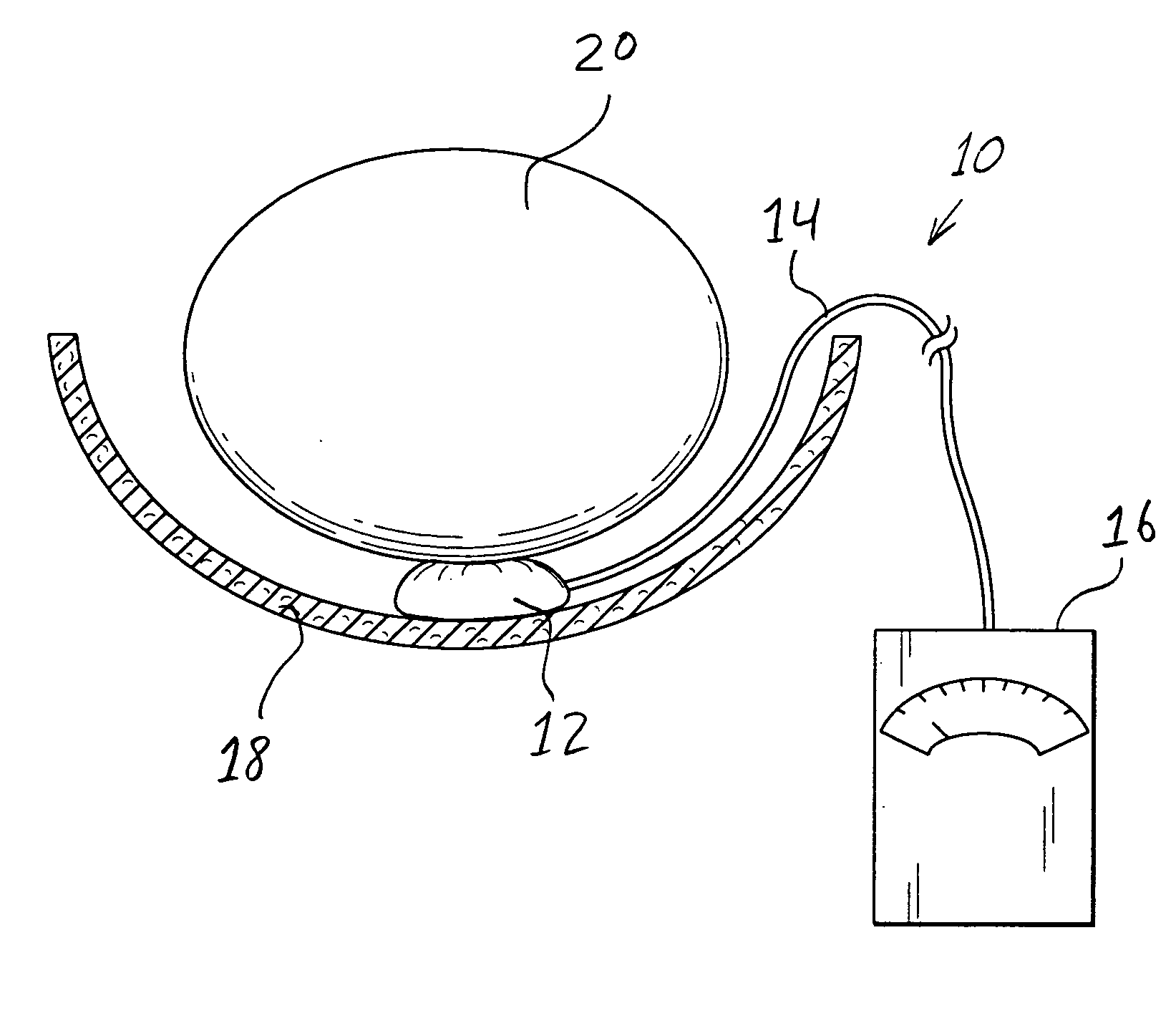
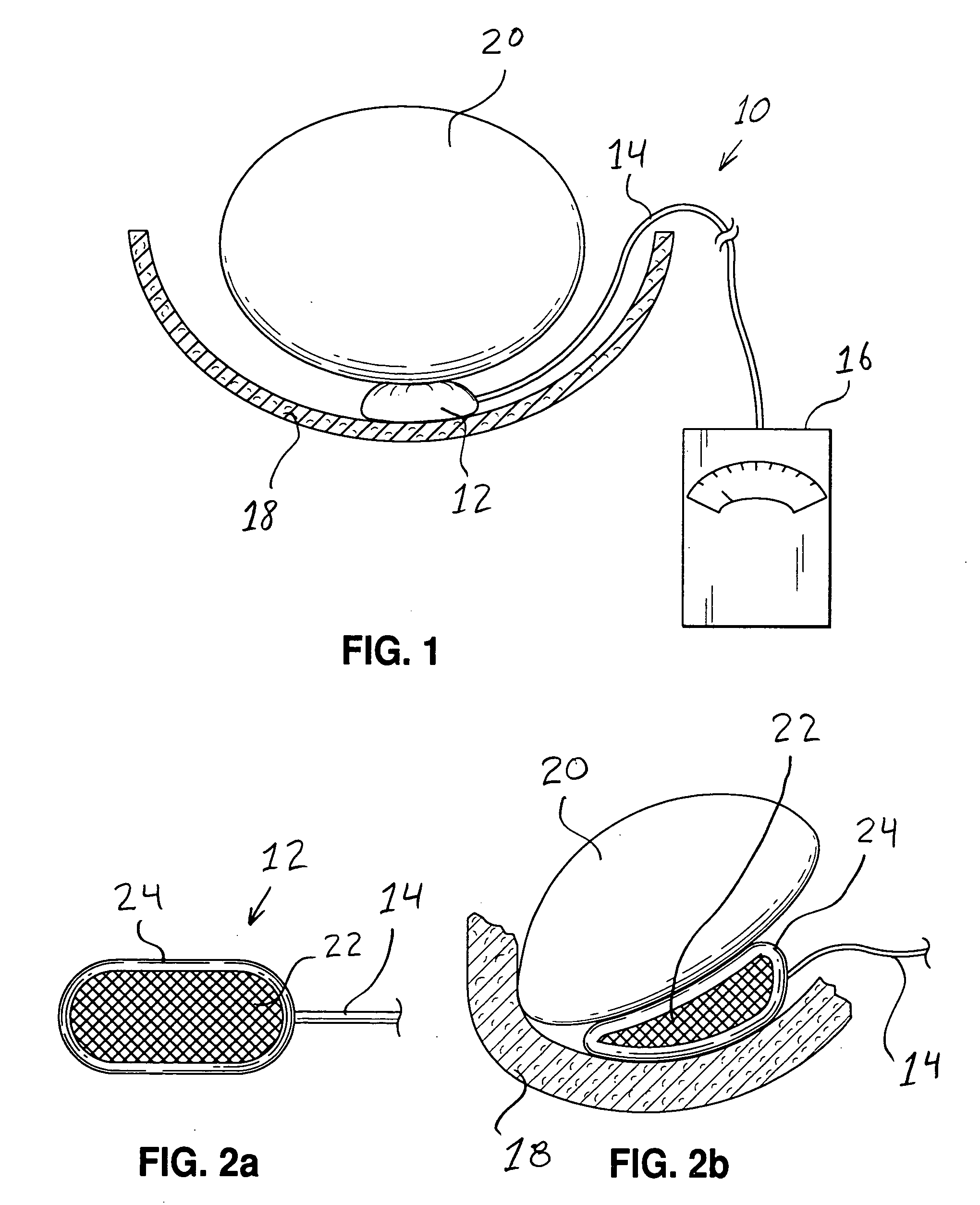
[0025] According to the first embodiment shown in FIG. 1, the surgical monitoring device 10 comprises a pressure or contact sensor 12 interposable between anatomical masses and / or anatomical structures 18, 20. The sensor 12 is operatively coupled via link or connection 14 to a monitor 16, the latter being operative to provide an indication ...


PUM


Abstract

Systems and methods for measuring the pressure exerted between or within anatomical masses/structures, as well as the position and/or spatial dimensions of an anatomical structure. According to a preferred embodiment, the invention comprises a sensor element positionable between anatomical structures or within an anatomical structure. The sensor is operative to generate a signal indicative of the pressure being exerted therebetween or therewithin. The sensor may be operative to measure spatial dimensions between structures or within a structure. A monitor coupled to the sensor receives a signal generated thereby and provides an indication as to the spacing or pressure being measured. The systems and methods may be utilized in diagnostic tests or surgical procedures.

Description

CROSS-REFERENCE TO RELATED APPLICATIONS [0001] The following application claims priority to Disclosure Document Number 520388 which was filed Oct. 23, 2002, the teachings of which are herein incorporated by reference. STATEMENT RE: FEDERALLY SPONSORED RESEARCH / DEVELOPMENT [0002] Not Applicable BACKGROUND OF THE INVENTION [0003] The relative positioning and pressure exerted by and between anatomical masses, structures, implants, and the like are often times crucial in assessing a patient's condition and making a proper diagnosis. In this regard, it is often of particular interest to determine the degree of pressure being exerted upon or by a particular type of anatomical structure, as well as whether or not the positioning of one or more structures is maintained in a proper orientation. For example, it is often ideal to measure the pressure capable of being exerted by either the urethral or anal sphincter, to thus assess sphincter tone, in making a diagnosis of urinary or fecal incon...

Claims


Application Information

Patent Timeline
Patent Type & Authority Applications(United States)
IPC IPC(8): A61B5/03A61B5/107A61B5/20
CPCA61B5/033A61B5/037A61B5/208A61B5/205A61B5/1076
Inventor BENDEREV, THEODORE
Owner BENDEREV THEODORE V
Why Eureka
Try Eureka