This helps you quickly interpret patents by identifying the three key elements:
Problems solved by technology
Method used
Benefits of technology
Benefits of technology
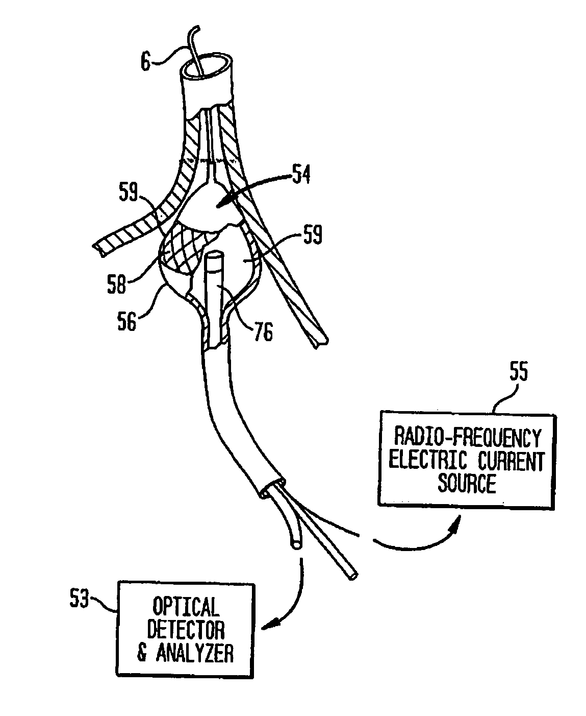
[0041] Optionally, a fluid can be disposable between the radiant energy delivery element and the target region. In one preferred embodiment a “projection balloon” is filled with a radiation-transmissive fluid so that radiant energy from the energy emitter can be efficiently passed through the instrument to the target region. The fluid can also be used to cool the energy emitter through conduction or via a closed or open circulator system. In certain applications, it can be desirable to used deuterium oxide (so-called “heavy water”) as a balloon-filling fluid medium because of its loss absorption characteristics vis-à-vis infrared radiation. In other applications, the inflation fluid can be water or saline or an admixture of such fluids with deuterium oxide (to enhance ablative energy transmission) and/or sodium diatrazoate (to enhance radiographic imaging).
[0042] It can also be desirable to emplo
Problems solved by technology
The regular pumping function of the atria is replaced by a disorganized, ineffective quivering as a result of chaotic conduction of electrical signals through the upper chambers of the heart.
Weakness, lightheadedness, fainting, heart failure, stroke and even death can result.
Although this procedure was successful in curing atrial fibrillation, the difficulty of the procedure, its invasive nature and the morbidity involved prevented its widespread adoption.
However, because of the difficulty in creating long lesions that were correctly located, continuous and transmural (through the heart wall) these devices have not achieved clinical or commercial success.
However, if the energy application is too deep in the vein, it can result in damage to the vein and resultant narrowing of the vein, called pulmonary vein stenosis, which has serious consequences and can be life threatening.
The correct positioning of the ablation device in the heart to obtain complete lesions that will provide conduction block without damaging sensitive tissues is complicated by the fact that the standard imaging technique available to the physician for the procedure is x-ray fluoroscopy which does a poor job of imaging soft tissues such as the heart and pulmonary veins.
X-ray contrast injection can be used to aid in imaging smaller arteries such as the coronary arteries but such injection is of very limited use when the entire heart or vessels as large as the pulmonary veins need to be imaged.
As a result, the physician using these ablation catheters has limited ability to understand the detailed anatomy of the vein and to understand how the ablation catheter is positioned in that anatomy.
Existing instruments for cardiac ablation suffer from a variety of design limitations.
In such devices, a major limitation in prior art percutaneous designs is their inability to maintain such contact with the
Method used
Image
Click on the blue label to locate the original text in one second.
Reading with bidirectional positioning of images and text.
Examples
Embodiment Construction
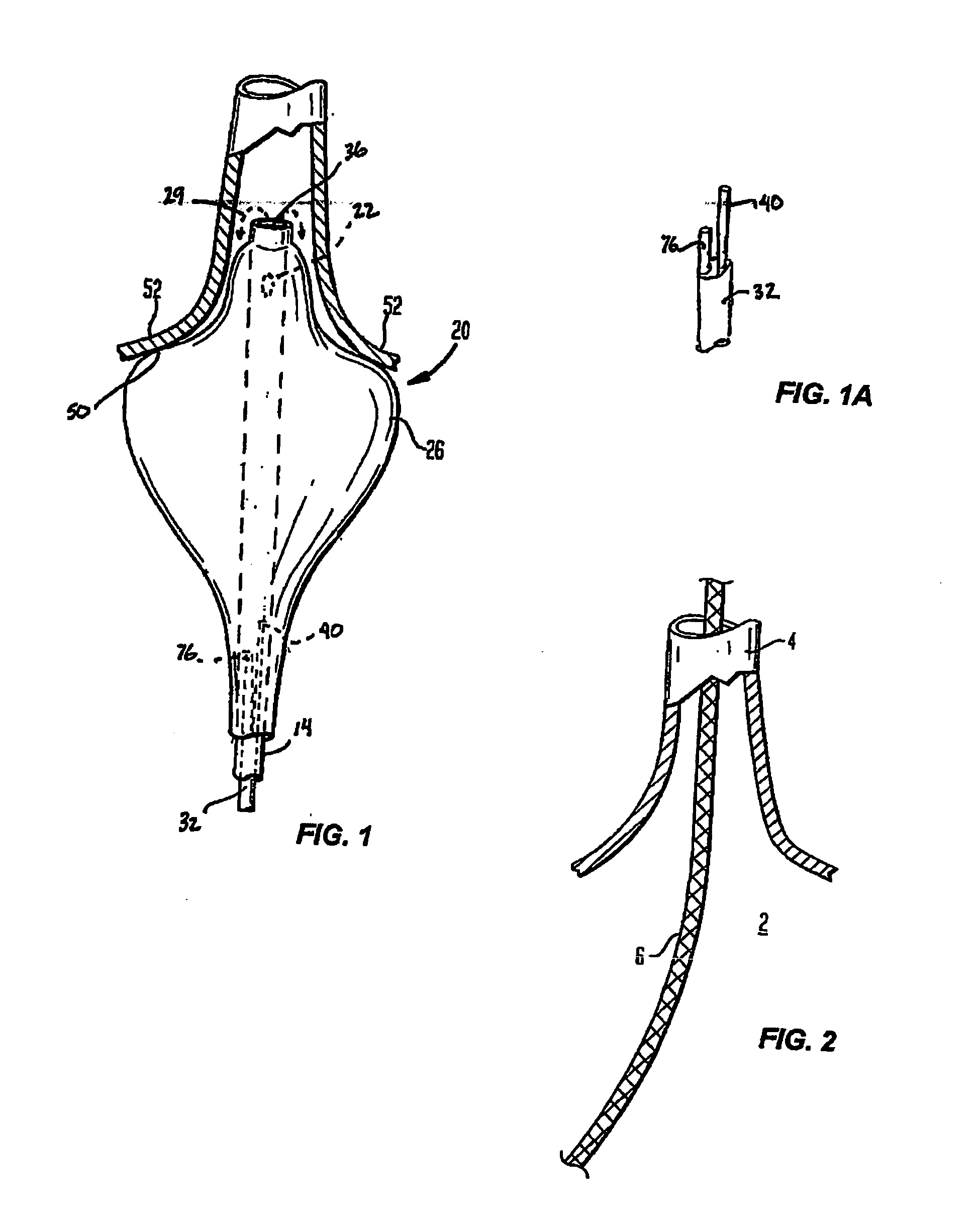
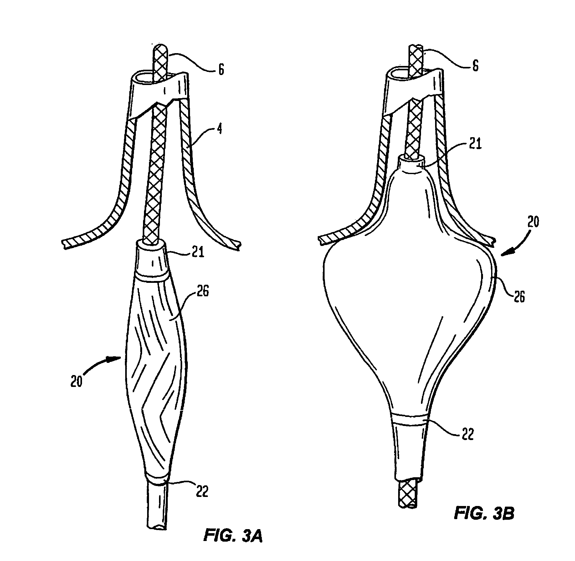
[0074]FIG. 1 provides a schematic, cross-sectional view of a coaxial catheter ablation instrument 20 according to the invention, including an elongate body 14 and a projection balloon 26 inflatable via one or more ports 22. The instrument is preferably designed such that upon disposition within the heart (e.g., proximal to a pulmonary vein), the projection balloon can be inflated such that a shoulder portion 50 of the balloon 26 will be urged into close proximity with a target region 52 of cardiac tissue (e.g. an annular region of the atrial heart wall surrounding the ostium of a pulmonary vein).
[0075] It should be understood that the embodiments illustrated in the drawings are only a few of the cardiac ablation instruments that can utilized the present invention. Further descriptions of other embodiments can be found, for example, in commonly owned, co-pending U.S. patent application Ser. No. 10 / 357,156, filed Feb. 3, 2003 and U.S. patent application Ser. No. 09 / 924,393, filed Aug...
PUM
Abstract
Guided ablation instruments are disclosed for creating lesions in tissue, especially cardiac tissue for treatment of arrhythmias, including atrial fibrillation. In one aspect of the invention, a percutaneous catheter is disclosed with an endoscope positionable in the instrument's distal end region to obtain an image. The image allows the clinician to determine whether contact has been achieved (or blood has been cleared from an ablative energy transmission path) before ablation begins or while ablation is occurring. In one embodiment, percutaneous ablation catheters are disclosed having at least one central lumen and one or more balloon structures at the distal end region of the instrument. Also disposed in the distal end region are an illuminating light source and an endoscope capable of collecting sufficient light to relay an image to the user. The instruments can further include an ablation element. The ablation element can be a contact ablation element, or a radiant energy emitter, which is preferably independently positionable within the lumen of the instrument and adapted to project ablative energy through a transmissive region of the instrument body (and/or balloon) to a target tissue site proximate to the pulmonary veins. The energy can delivered without the need for contact between the energy emitter and the target tissue so long as a clear transmission pathway is established. The endoscope element of the instrument allows the clinician to determine the position of the instrument and, if radiant energy is to be employed, see if such a pathway is clear. Moreover, because the position of the radiant energy emitter can be varied, endoscopic guidance permits the clinician to select a desired location and dose for the lesion.
Description
CROSS-REFERENCE TO RELATED APPLICATIONS [0001] This application claims priority of U.S. Provisional Patent Application Ser. No. 60 / 477,374, filed Jun. 10, 2003. [0002] This application is a continuation-in part of U.S. patent application Ser. No. 10 / 357,156, filed Feb. 3, 2003, which is a continuation-in-part of U.S. patent application Ser. No. 09 / 924,393, filed on Aug. 7, 2001. [0003] This application is also a continuation-in-part of U.S. patent application Ser. No. 10 / 674,114, filed Sep. 29, 2003, which is a continuation of U.S. patent application Ser. No. 09 / 616,275 filed Jul. 14, 2000, now U.S. Pat. No. 6,626,900, which is a continuation-in-part of U.S. patent application Ser. No. 09 / 602,420 filed Jun. 23, 2000, now U.S. Pat. No. 6,572,609, which is a continuation-in-part of U.S. patent application Ser. No. 09 / 357,355, filed on Jul. 14, 1999, now U.S. Pat. No. 6,423,055 issued Jul. 22, 2002. [0004] The teachings of all of these prior related applications are hereby expressly in...
Claims
Application Information
Patent Timeline
Application Date:The date an application was filed.
Publication Date:The date a patent or application was officially published.
First Publication Date:The earliest publication date of a patent with the same application number.
Issue Date:Publication date of the patent grant document.
PCT Entry Date:The Entry date of PCT National Phase.
Estimated Expiry Date:The statutory expiry date of a patent right according to the Patent Law, and it is the longest term of protection that the patent right can achieve without the termination of the patent right due to other reasons(Term extension factor has been taken into account ).
Invalid Date:Actual expiry date is based on effective date or publication date of legal transaction data of invalid patent.

