Fuel supply system and fuel supply method for in-cylinder direct fuel injection engine

a fuel injection engine and fuel supply technology, which is applied in the direction of machines/engines, combustion air/fuel air treatment, electric control, etc., can solve the problems of limiting the dynamic range and increasing the output, and achieve the effect of higher outpu

Inactive Publication Date: 2005-03-31
HITACHI LTD
View PDF14 Cites 128 Cited by
  • Summary
  • Abstract
  • Description
  • Claims
  • Application Information

AI Technical Summary

Benefits of technology

[0010] The present invention is to solve the above problems and to provide a fuel supply system and method for in-cylinder direct fuel injection engine that realizes higher output.

Problems solved by technology

However, on the prior art, there has been limitations in extending the dynamic range and increasing the output by utilizing only supercharger on the direct fuel injection engine.

Method used


Image

  • Fuel supply system and fuel supply method for in-cylinder direct fuel injection engine
  • Fuel supply system and fuel supply method for in-cylinder direct fuel injection engine
  • Fuel supply system and fuel supply method for in-cylinder direct fuel injection engine

Examples


Embodiment Construction

[0055] An embodiment of the fuel supply system for in-cylinder direct fuel injection engine according to the present invention will be described hereunder, using figures.

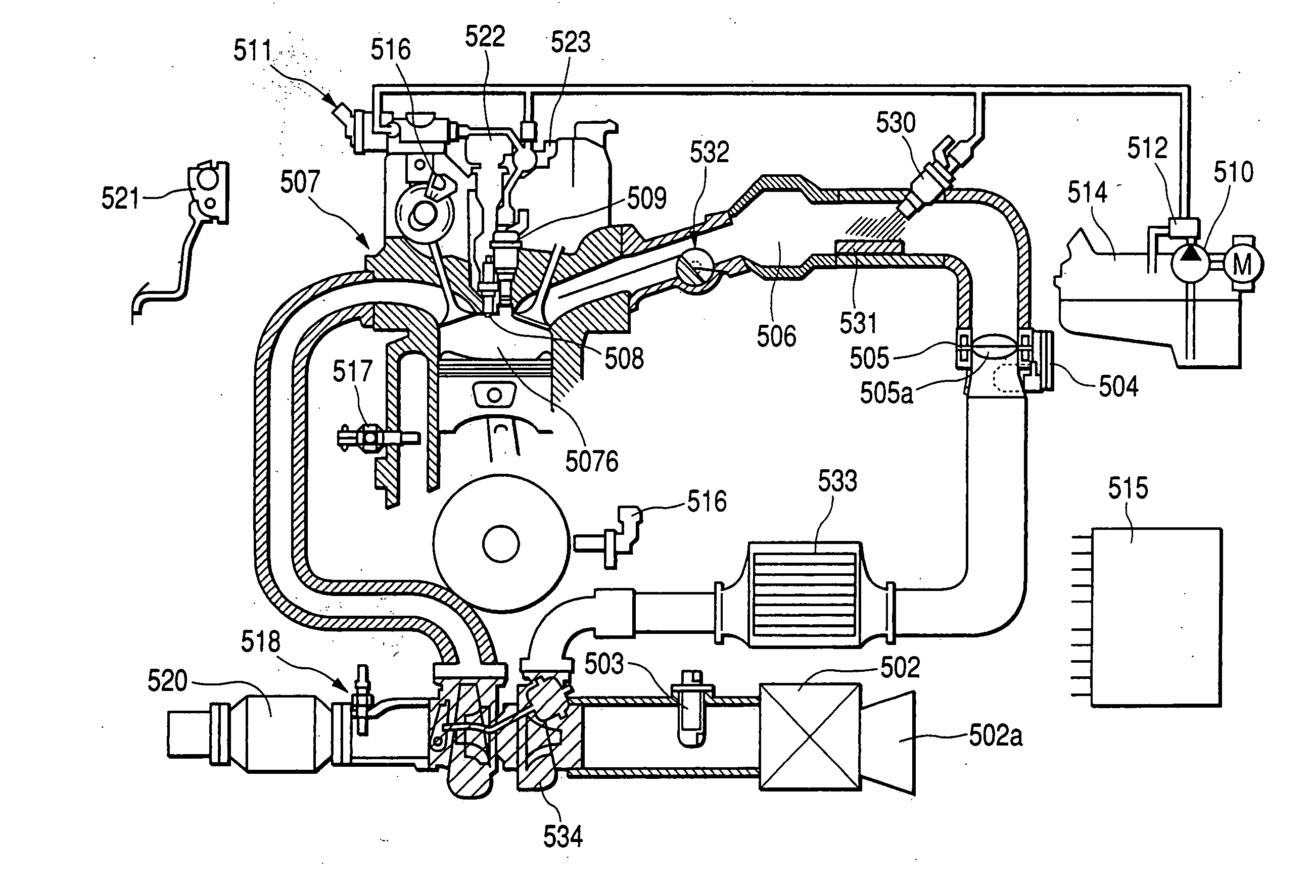
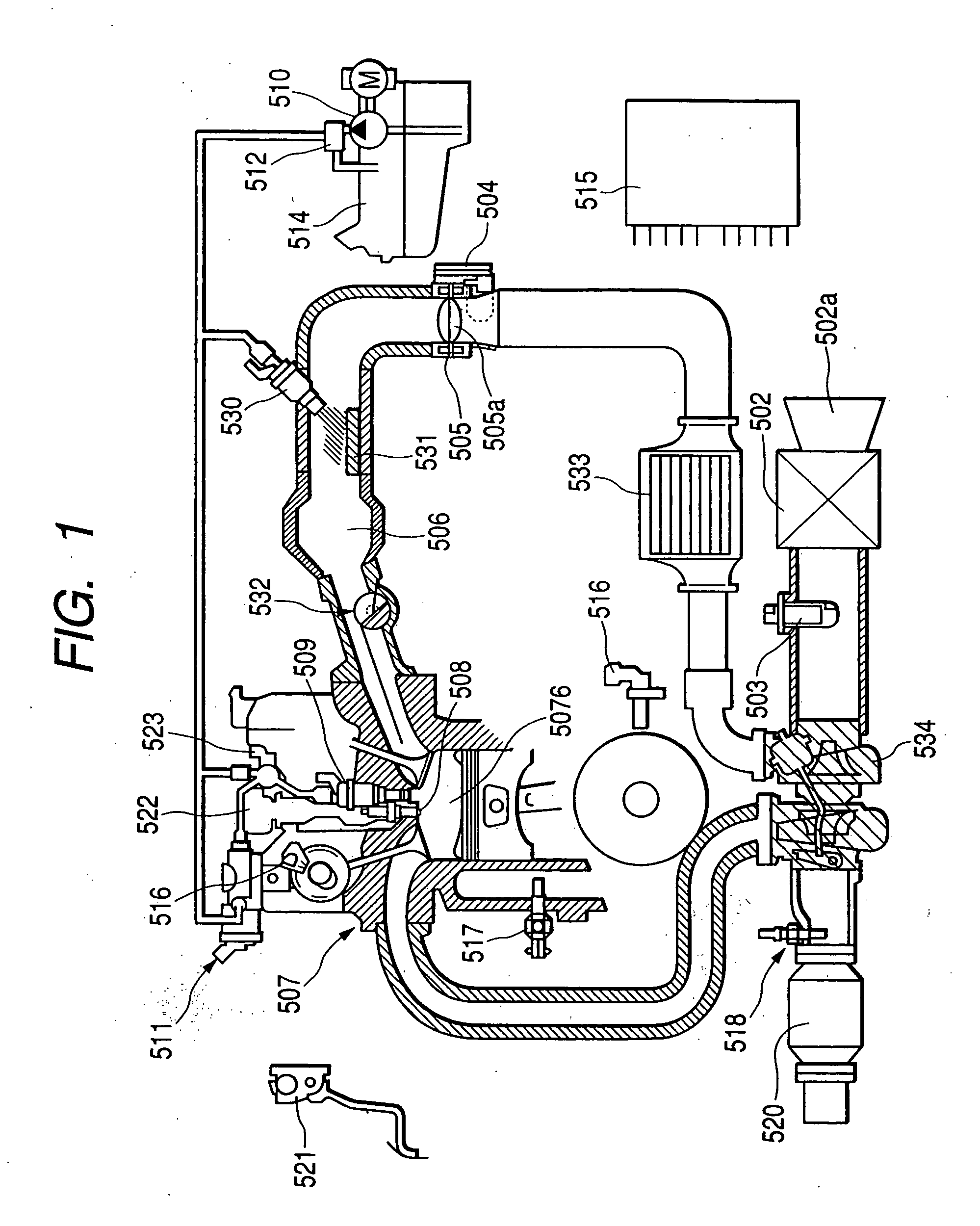
[0056]FIG. 1 shows the overall system construction of a direct injection engine 507. Air to be directed into the cylinder 507b (of which air flow is defined as Qc) is taken in from the inlet 502a of an air cleaner 502. The air is passed through an air flow sensor 503 as one of the means for measuring the operating condition of the engine, pressurized by a supercharger 534, and then passed through an intercooler 533, passed through a throttle body 505, in which an electronic control throttle valve 505a for controlling the intake air flow rate is installed. And then the air enters a collector 506. The airflow sensor outputs a signal showing the intake air flow rate to a control unit 515-engine controller.

[0057] A throttle sensor 504 for sensing the position of the electronic control throttle valve is installed in th...


PUM


Abstract

To offer a fuel supply system and fuel supply method for direct injection engine that realizes higher output. In a fuel supply system for direct injection engine of the present invention, equipped with a primary fuel injector that injects fuel directly into the cylinder of the direct injection engine and supercharger that increase the intake air quantity of the engine, a secondary fuel injector is installed in addition to the primary fuel injector. In a specified engine load area, fuel is supplied using the primary fuel injector and secondary fuel injector. Even though the fuel quantity injected from the primary fuel injector into the cylinder is limited, the fuel supply system for direct injection engine constructed as above can increase the engine output because the fuel insufficiency can be supplied by the secondary fuel injector.

Description

CLAIM OF PRIORITTY [0001] The present application claims priority from Japanese application serial no. 2003-206652, filed on Aug. 8, 2003), the content of which is hereby incorporated by reference into this application. FIELD OF THE INVENTION [0002] The present invention relates to a fuel supply system and a fuel supply method for in-cylinder direct fuel injection engine. BACKGROUND OF THE INVENTION [0003] For example, U.S. Patent Publication No. 5894832 has proposed heating and vaporizing fuel supplied from a fuel injector by a heater installed in an intake passage so as to reduce fuel adhesion onto the intake passage and an intake valve, thereby improving combustion and reducing emissions of hydrocarbon at the time of cold start of an engine particularly. [0004] Japanese Application Patent Laid-Open Publication No. Hei 11-166421 have proposed, instead of a port injection engine that fuel is injected at an intake port, an in-cylinder direct fuel injection engine that fuel is inject...

Claims


Application Information

Patent Timeline
Patent Type & Authority Applications(United States)
IPC IPC(8): F02M37/00F01N3/20F01N3/24F02B23/10F02B29/04F02B37/00F02B75/12F02D23/00F02D41/00F02D41/02F02D41/04F02D45/00F02M31/135F02M45/02F02M53/02F02M61/14F02M63/00F02M69/00F02M69/04F02M69/30
CPCF02B29/0406Y02T10/126F02B2023/106F02B2075/125F02B2275/16F02D41/0007F02D41/3094F02M31/135F02M45/02F02M61/14F02M69/044F02M69/046F02M69/30Y02T10/123Y02T10/144F02B37/00Y02T10/12
Inventor SHIMADA, KOSAKUICHIHARA, TAKANOBU
Owner HITACHI LTD
Why Eureka
Try Eureka