
Capacitor discharge ignition device

a technology of capacitor discharge and ignition device, which is applied in the direction of ignition safety means, electric control, machines/engines, etc., can solve the problems of complex circuit configuration, device cost, and inability to ignite combustion engines, and achieve the effect of simple circuit configuration

Active Publication Date: 2005-03-31
MITSUBISHI ELECTRIC CORP
View PDF2 Cites 7 Cited by
  • Summary
  • Abstract
  • Description
  • Claims
  • Application Information

AI Technical Summary

Benefits of technology

The present invention provides a capacitor discharge ignition device that can easily detect abnormalities in the ignition circuit. The device uses a capacitor to store and release charge to generate ignition energy, and ignition timing control means to supply an ignition signal to the device. A circuit abnormality detecting means measures the voltage of the capacitor at specific timing and determines if there is an abnormality in the circuit. This allows for easy diagnosis of failure in the charging or discharge circuit. The device is simple in construction and can effectively detect abnormalities in the ignition circuit.

Problems solved by technology

If an abnormality such as a disconnection in a discharge circuit exists from the capacitor to the ignition primary coil, charge is not released to the ignition primary coil and hence the internal combustion engine cannot be ignited.
However, those methods have problems that the circuit configuration is complex and the device is expensive for the limited purpose of detecting an abnormality in an ignition circuit because, for example, circuits and elements for measurement need to be added and a peak hold circuit needs to be added because of short duration of a phenomenon.

Method used


Image

  • Capacitor discharge ignition device
  • Capacitor discharge ignition device
  • Capacitor discharge ignition device

Examples


embodiment 1

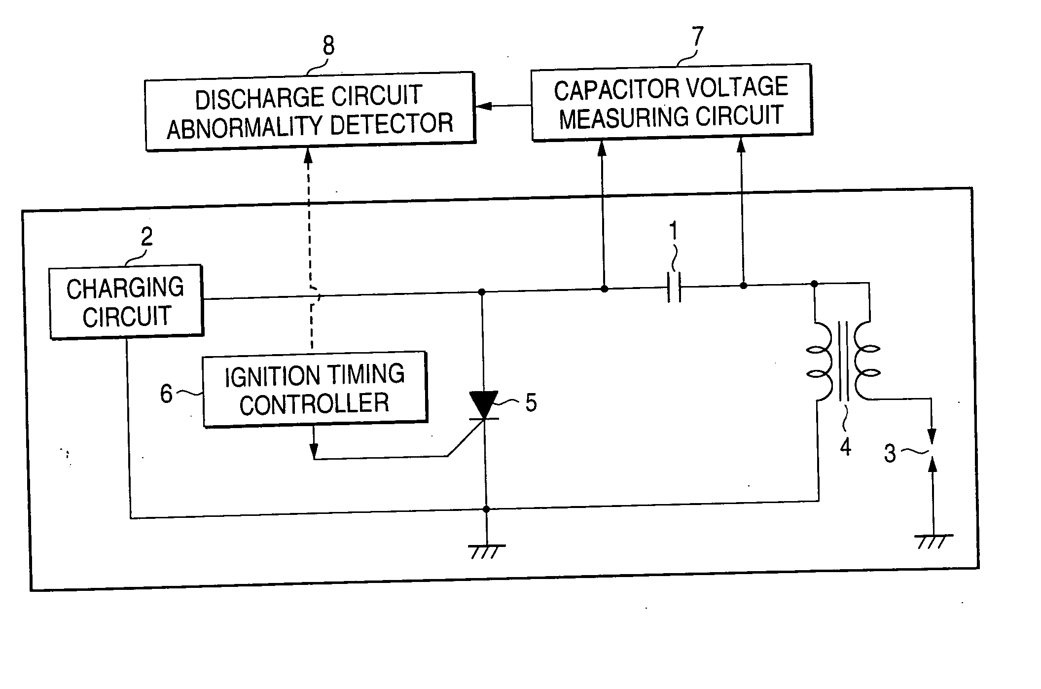
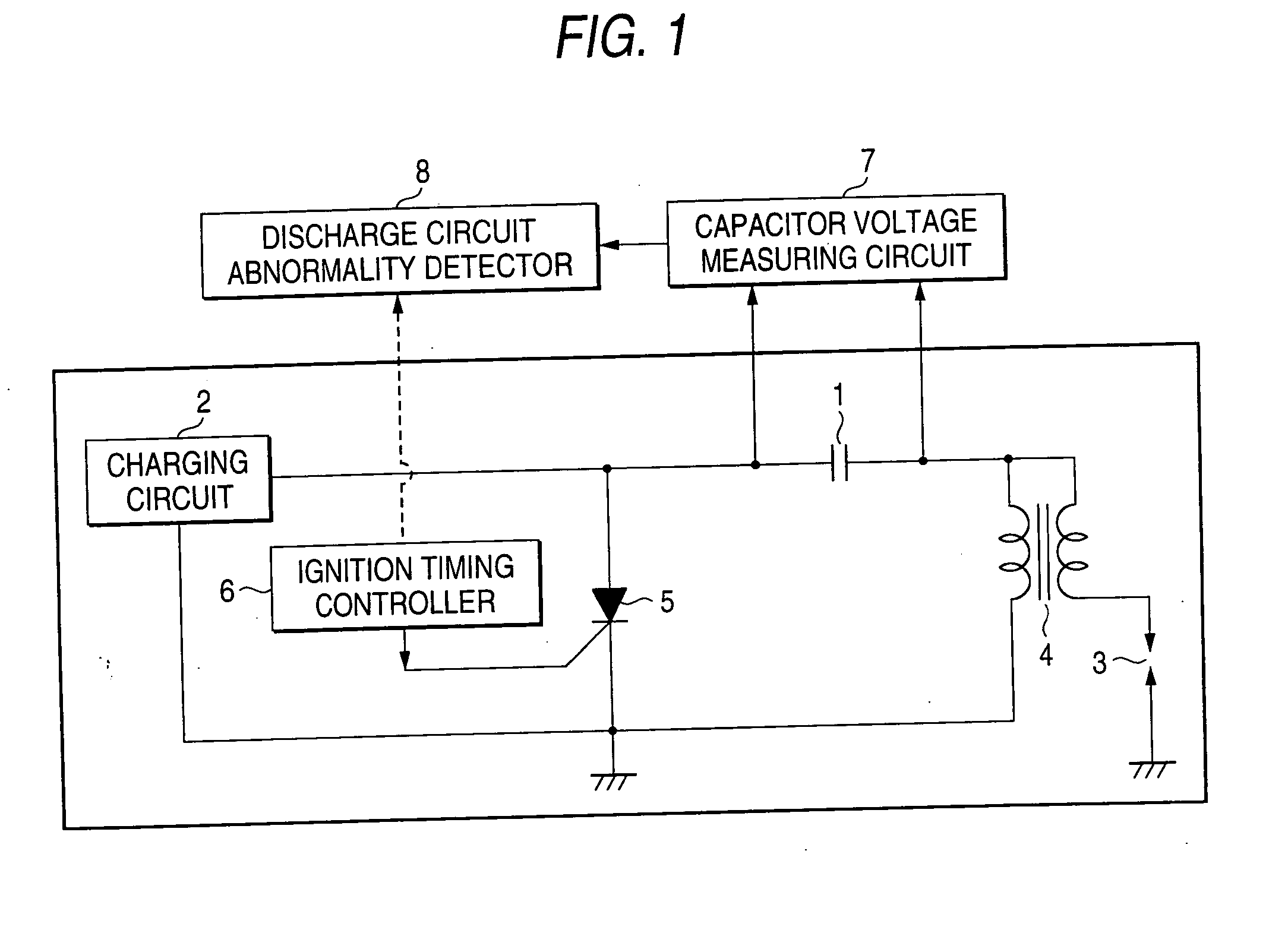
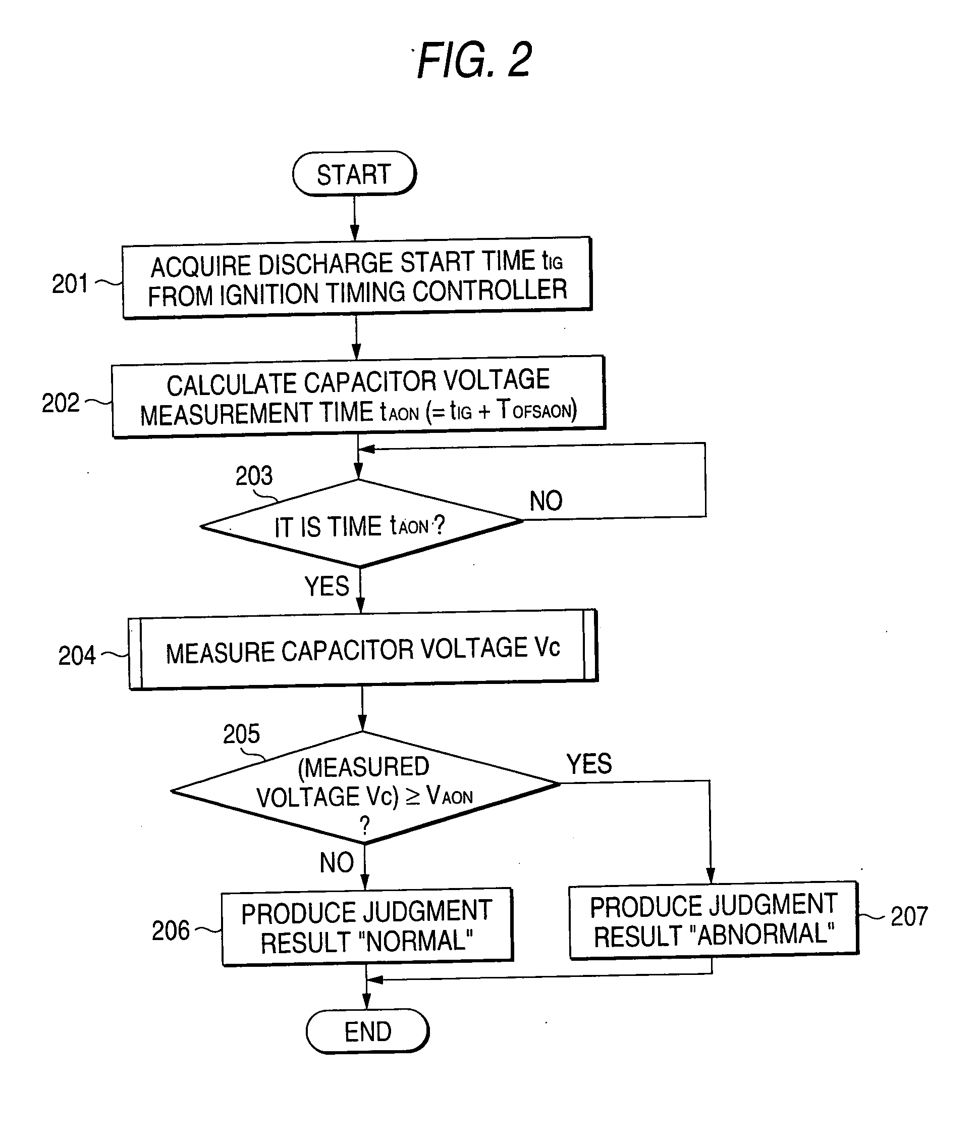
[0017]FIGS. 1-3 are for description of a capacitor discharge ignition device according to a first embodiment of the present invention. More specifically, FIG. 1 is a circuit diagram showing the configuration of the capacitor discharge ignition device and FIGS. 2 and 3 are a flowchart and a time chart, respectively, showing its operation. As shown in FIG. 1, the capacitor discharge ignition device according to this embodiment is composed of a capacitor 1 for storing charge to produce ignition energy, a charging circuit 2 as a DC power source for charging the capacitor 1, ignition coils 4 connected to an ignition plug 3, a switching element 5 for supplying the charge stored in the capacitor 1 to the primary side of the ignition coils 4, an ignition timing controller 6 for determining ignition timing on the basis of a received crank angle signal of an internal combustion engine and producing a signal for driving the switching element 5 at an ignition time, a capacitor voltage measuring...

embodiment 2

[0023]FIGS. 4A and 4B and FIG. 5 are flowcharts and a time chart, respectively, showing the operation of a capacitor discharge ignition device according to a second embodiment of the invention. In the capacitor discharge ignition device according to this embodiment, unlike in the case of the first embodiment, the timing for measuring and judging a capacitor voltage is determined by using the crank angle signal that is input to the ignition timing controller 6 without calculating a measurement time. It is intended to obtain the same advantages as of the first embodiment with a simpler configuration. Whereas the circuit configuration is the same as shown in FIG. 1, not only the ignition signal that is produced on the basis of the crank angle signal generated by a crank angle sensor but also the crank angle signal as a timing signal for voltage measurement is input from the ignition timing controller 6 to the discharge circuit abnormality detector 8. This will be described below with r...

embodiment 3

[0027]FIGS. 6-8 are for description of a capacitor discharge ignition device according to a third embodiment of the invention. More specifically, FIG. 6 is a circuit diagram showing the configuration of the capacitor discharge ignition device and FIGS. 7 and 8 are a flowchart and a time chart, respectively, showing its operation. The capacitor discharge ignition device according to this embodiment is different from that according to the first embodiment in that the former detects an abnormality in the charging circuit 2 and the discharge circuit for the capacitor 1. The circuit diagram of FIG. 6 is different from that of FIG. 1 in that the discharge circuit abnormality detector 8 of the latter is replaced by a charging / discharge circuit abnormality detector 9.

[0028] As in the case of the first embodiment, the voltage between the two terminals of the capacitor 1 is monitored by the capacitor voltage measuring circuit 7. The monitored voltage is input to the charging / discharge circui...


PUM


Abstract

A capacitor discharge ignition device is provided with a capacitor for storing charge to produce ignition energy; ignition coils that receive charge released from the capacitor on the primary side and generate a high voltage on the secondary side; a switching element for causing the capacitor to release the charge stored therein to the ignition coils; ignition timing control means that receives a signal corresponding to a crank angle of an internal combustion engine and supplies an ignition signal to the switching element; and circuit abnormality detecting means that receives a signal from the ignition timing control means, sets a capacitor voltage measurement time, and judges for a circuit abnormality on the basis of a voltage of the capacitor measured at the capacitor voltage measurement time.

Description

BACKGROUND OF THE INVENTION [0001] 1. Field of the Invention [0002] The present invention relates to detection of an abnormality in a capacitor discharge ignition device that is used for igniting an internal combustion engine. [0003] 2. Description of the Related Art [0004] In capacitor discharge ignition devices used for igniting an internal combustion engine, a capacitor for ignition is charged to a prescribed voltage before an ignition time and the resulting charge is released to an ignition primary coil at the ignition time, whereby a high voltage is induced across an ignition secondary coil. Therefore, the capacitor has been charged to the prescribed voltage or more at an instant immediately before the ignition time and the voltage of the capacitor decreases and becomes approximately equal to 0 V after the ignition and before a start of charging for the next ignition. If an abnormality such as a disconnection in a discharge circuit exists from the capacitor to the ignition prim...

Claims


Application Information

Patent Timeline
Patent Type & Authority Applications(United States)
IPC IPC(8): F02P11/00F02D45/00F02P3/08F02P17/00
CPCF02P17/00F02P3/0807
Inventor UMINO, HIROSHIUMEMOTO, HIDEKI
Owner MITSUBISHI ELECTRIC CORP
Learn More