Heat conductive seat with liquid

a conductive seat and heat sinking technology, applied in the direction of cooling/ventilation/heating modifications, semiconductor/solid-state device details, semiconductor devices, etc., can solve the problems of increasing the heat sinking efficiency, affecting the normal operation of a personal computer, and the conductance rate of the material of the heat sink, so as to increase the heat sinking effect, and the effect of rapid and uniform transmission

Inactive Publication Date: 2005-03-31
GLACIALTECH
View PDF16 Cites 5 Cited by
  • Summary
  • Abstract
  • Description
  • Claims
  • Application Information

AI Technical Summary

Benefits of technology

[0007] The heat conductive seat with liquid of the present invention provides a plurality of strip members in the bottom area of a base having liquid therein using principles of capillarity and heat pipe, flow channels are formed from the strip members on the bottom of the latter and are mutually spaced, a return area is formed between the tops of the strip members and a lid; when in use, the bottom of the base contacts with a heat-generating source, and the top of the base contacts with a heat sink, the liquid sealed in the base and absorbing the latent heat from the heat-generating source becomes a vapor flow flowing toward the return area; when the vapor flow uniformly returns to the contact areas of the heat sink with the top of the base, it condenses by heat discharging into liquid and drops into the flow channels to repeatedl

Problems solved by technology

Thereby, operating efficiency of a heat sink used for a microprocessor will directly affect the capability of maintaining in a normal range of working temperature of the microprocessor; this further affects normal operation of a personal computer.
However, no matter the heat-sinking fins of the heat sink are integrally formed of aluminum or of copper, the entire heat sink and the heat-generating source

Method used


Image

  • Heat conductive seat with liquid
  • Heat conductive seat with liquid
  • Heat conductive seat with liquid

Examples


Embodiment Construction

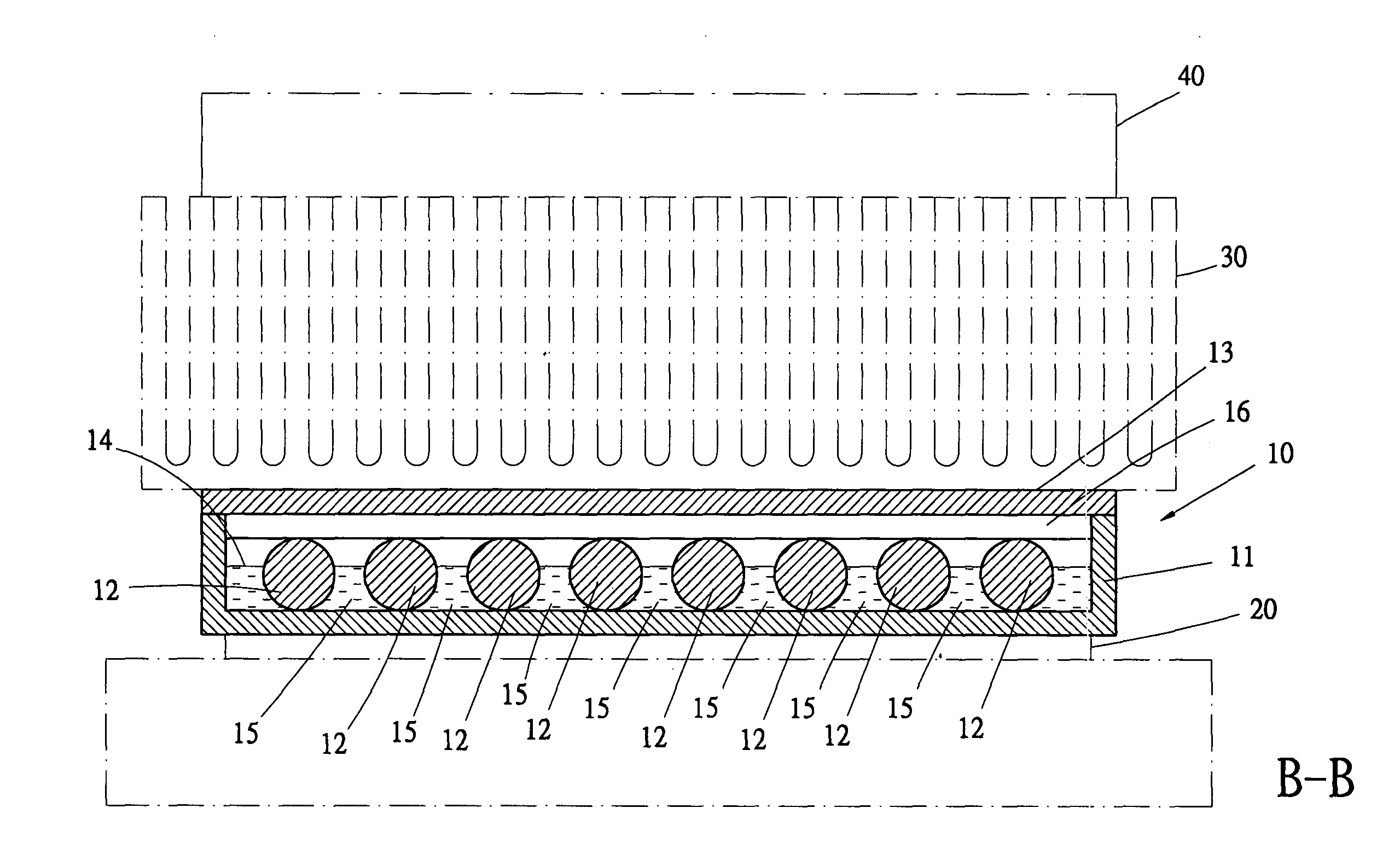
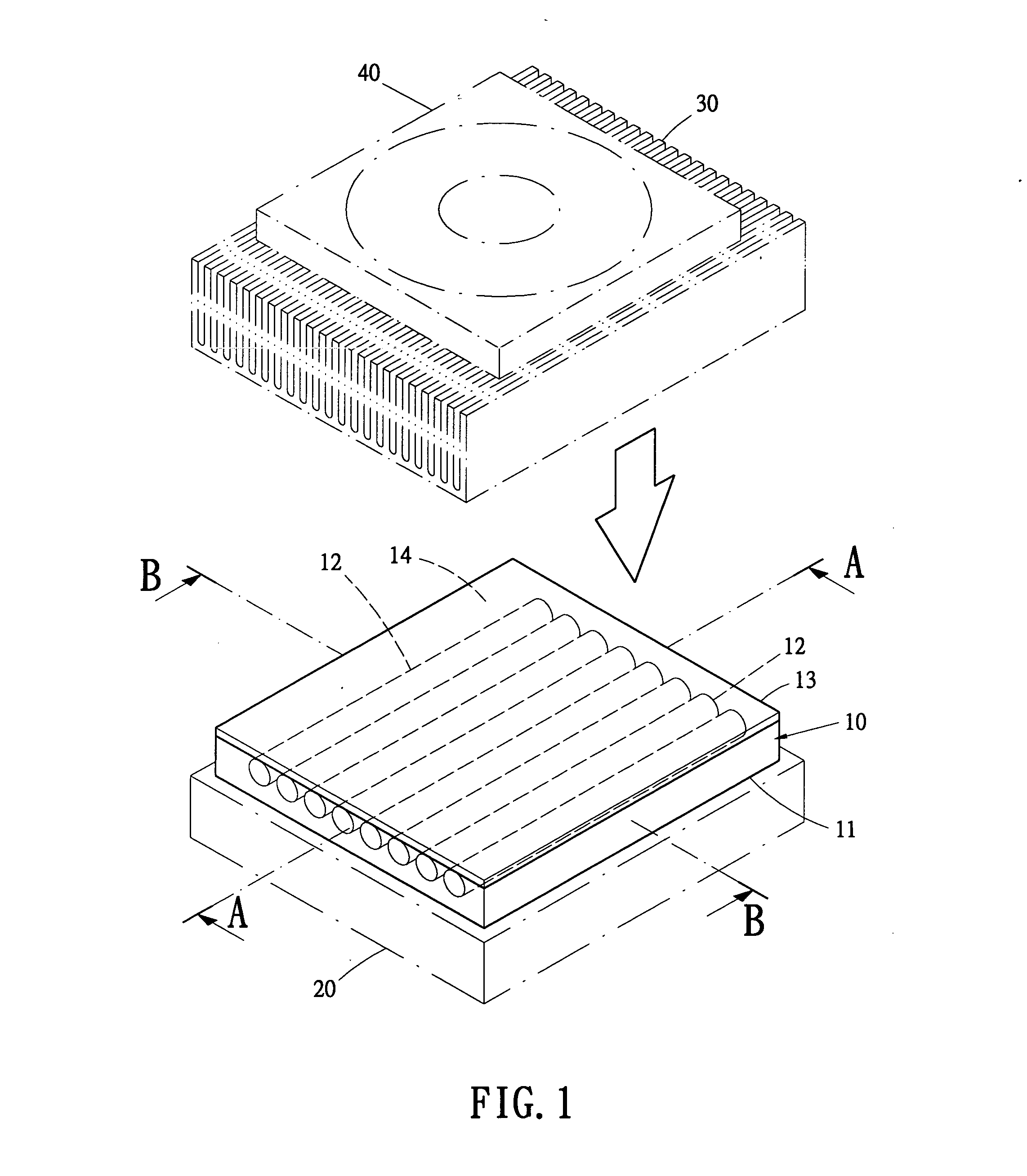
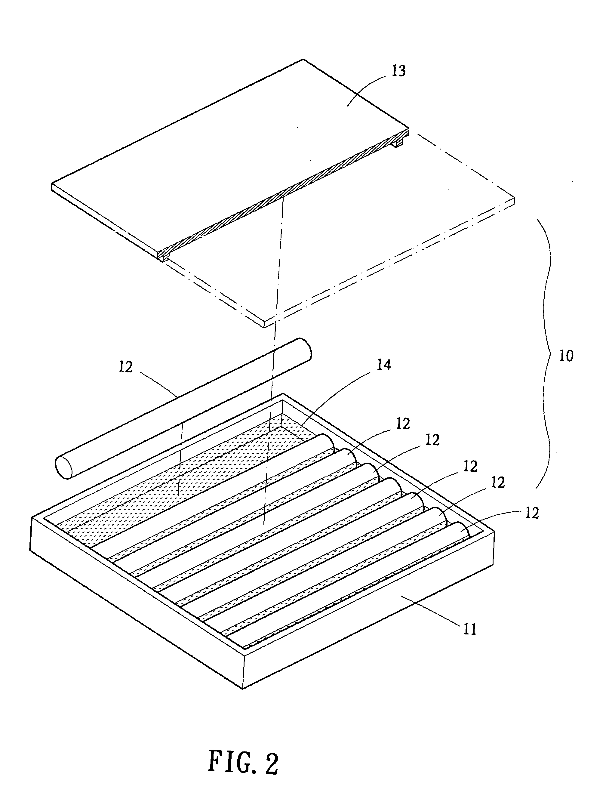
[0020] The basic structure of the heat conductive seat with liquid of the present invention is as shown in FIGS. 1 and 2, wherein the heat conductive seat 10 has a recessed box like base 11 as a main body thereof, the base 11 is fixedly provided therein with a plurality of strip members 12, a lid 13 is provided to cover the base 11; the base 11 is sealed therein with liquid 14 composed of water, methanol or cooling medium to form a heat conductive member used between a heat-generating source 20 and a heat sink 30 to fast transmit the heat source to the heat sink 30 uniformly, and a fan 40 is provided on the heat sink 30 to generate air flow to get an object of fast heat sinking.

[0021] Referring simultaneously to FIGS. 3 and 4, the strip members 12 provided in the base 11 are strip-like structure portions with their sections wider in the middles and tapering to the top and bottom ends thereof; the strip members 12 are mutually parallelly provided in the bottom area of the base 11, f...


PUM


Abstract

The conductive seat has parallelly arranged strip members in a bottom area of its base sealed therein with liquid, a plurality of flow channels are formed from and on the bottom of the strip members and are mutually spaced; a return area is formed between the top ends of the strip members and the lid; when the bottom of the base contacts with a heat-generating source, the liquid sealed in the base and absorbing the latent heat from the heat-generating source becomes a vapor flow flowing toward the return area to repeatedly circulate and transmit the heat, thereby the heat is rapidly and uniformly transmitted to the heat sink to further increase the effect of heat sinking.

Description

BACKGROUND OF THE INVENTION [0001] 1. Field of the Invention [0002] The present invention is related to a heat conductive seat with liquid therein, and especially related to a heat conductive member used between a heat-generating source and a heat sink applying the principles of capillarity and heat pipe to fast transmit the heat source formed by the heat-generating source to the heat sink, this can elevate the effect of heat sinking. [0003] 2. Description of the Prior Art [0004] Microprocessors (CPU's) used on personal computers nowadays not only shall be developed in pursuance of the requirements of the application fields of Internet and multimedia etc., but also even shall be developed more in pursuance of highly efficient operation of timing pulses for market promotion nowadays; under such a tendency certainly, we shall pay attention more to the feature of heat sinking of a microprocessor itself in designing its packing, so that in high speed operation of the microprocessor, pos...

Claims


Application Information

Patent Timeline
IPC IPC(8): H01L23/427H05K7/20
CPCH01L23/427H01L2924/0002H01L2924/00
Inventor HUANG, RONG-FUNGTSAI, PEI-SUNGDOU, YUE-JING
Owner GLACIALTECH
Why Eureka
Try Eureka