Vehicle drive system

a technology of drive system and vehicle, which is applied in the direction of vehicle position/course/altitude control, process and machine control, instruments, etc., can solve the problems of large motor size, and achieve the effect of large output capacity, high torque and sufficient torqu

Inactive Publication Date: 2005-03-31
NISSAN MOTOR CO LTD
View PDF20 Cites 13 Cited by
  • Summary
  • Abstract
  • Description
  • Claims
  • Application Information

AI Technical Summary

Benefits of technology

[0006] It has been discovered that, when the motor-driven wheels that are not driven by the engine are driven with a single electric motor as disclosed in the conventional vehicle drive system in the above mentioned reference, the electric motor is required to have a large output capacity in order to provide both high torque at low rotational speeds and sufficient torque at medium to high rotational speeds. One feasible method of increasing the output of the electric motor is to increase the number of coil windings and raise the magnetic flux of the motor. However, increasing the number of coil windings causes the size of the motor to become large.
[0007] The present invention was conceived in view of the above mentioned problem, and one object of the present invention is to provide a vehicle drive system that is capable of sufficiently accommodating rotational speeds ranging from low speeds to high speeds while preventing size of the drive sources from becoming large.

Problems solved by technology

However, increasing the number of coil windings causes the size of the motor to become large.

Method used


Image

  • Vehicle drive system
  • Vehicle drive system
  • Vehicle drive system

Examples


Embodiment Construction

[0017] Selected embodiment of the present invention will now be explained with reference to the drawings. It will be apparent to those skilled in the art from this disclosure that the following description of the embodiment of the present invention is provided for illustration only and not for the purpose of limiting the invention as defined by the appended claims and their equivalents.

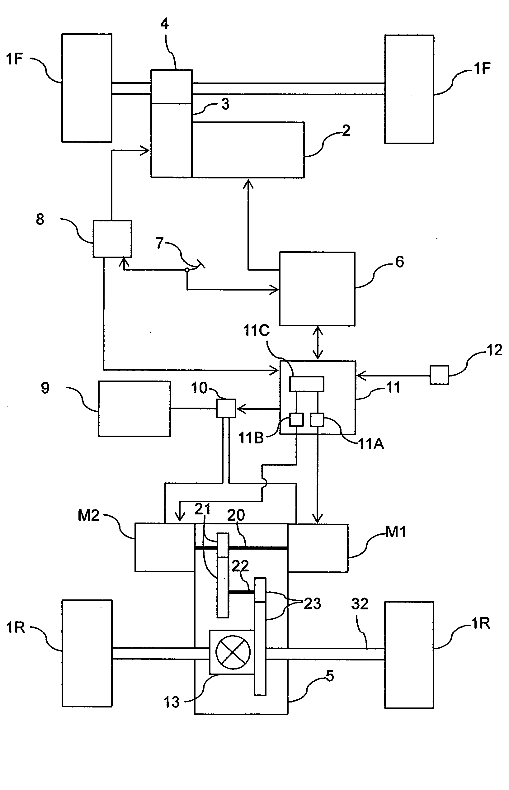
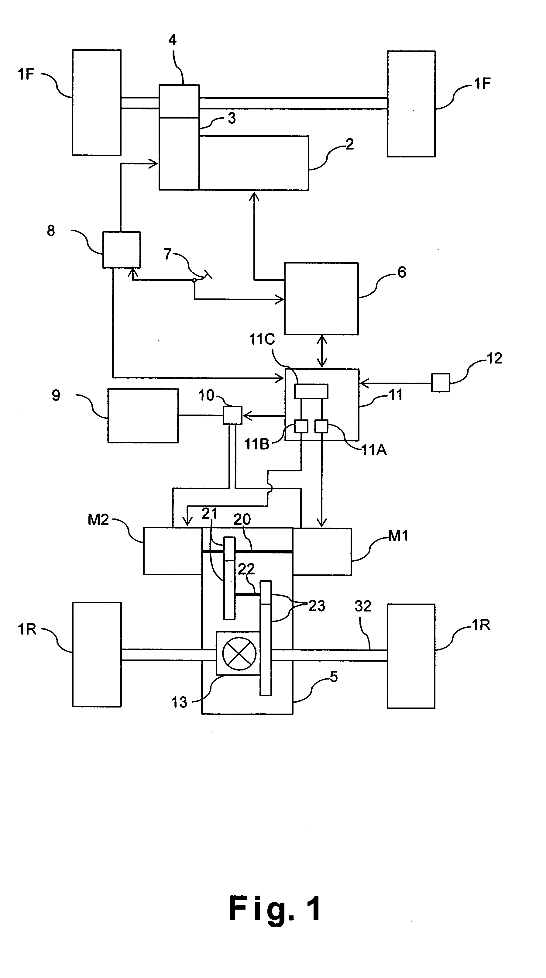
[0018] Referring initially to FIG. 1, a vehicle drive system is illustrated in accordance with one embodiment of the present invention. FIG. 1 is a schematic block diagram illustrating the vehicle drive system of the one embodiment.

[0019] As seen in FIG. 1, in this embodiment of the present invention, the vehicle drive system is preferably applied to a four-wheel drive vehicle in which a pair of left and right front wheels 1F is driven by an engine 2 and a pair of left and right rear wheels 1R is driven by a first electric motor M1 and / or a second electric motor M2. Moreover, the output of the engin...


PUM


Abstract

In a vehicle drive system, a pair of rear wheels is driven by first and second motors. The first motor is designed to specifications suited to delivering torque at low rotational speeds and the second motor is designed to specifications suited to delivering torque at high rotational speeds. The motor used to drive the rear wheels is selected based on the vehicle speed. The change in the operations of the first and second motors is synchronized with a shifting of a transmission disposed between an engine and a pair of front wheels. Thus, the vehicle drive system is configured and arranged to accommodate speeds ranging from low speeds to high speeds in a sufficient manner without requiring the drive source to become large.

Description

BACKGROUND OF THE INVENTION [0001] 1. Field of the Invention [0002] The present invention relates to a vehicle drive system configured and arranged to drive a pair of front wheels and a pair of rear wheels of a vehicle with different drive sources. [0003] 2. Background Information [0004] One example of a conventional vehicle drive system configured such that the front and rear wheels can be driven with a plurality of drive sources is disclosed in Japanese Laid-Open Utility Model Publication No. 55-138129. This reference discloses a four-wheel drive vehicle in which one of a pair of front wheels or a pair of rear wheels is driven with an engine and the other pair of wheels that is not driven with the engine is driven with a motor. [0005] In view of the above, it will be apparent to those skilled in the art from this disclosure that there exists a need for an improved vehicle drive system. This invention addresses this need in the art as well as other needs, which will become apparent...

Claims


Application Information

Patent Timeline
Patent Type & Authority Applications(United States)
IPC IPC(8): B60K1/02B60W20/00B60K6/26B60K6/44B60K6/52B60K6/54B60K6/547B60K17/00B60K17/356B60L50/16B60W10/04B60W10/06B60W10/08B60W10/10B60W10/11F16H61/00F16H61/68F16H63/40
CPCB60K1/02B60K6/48B60K6/52B60K6/547B60W10/08Y02T10/6265B60W20/00B60W2520/10Y02T10/6221Y10S903/945B60W10/10Y02T10/62B60K17/00B60W20/30B60K17/34
Inventor SHIMIZU, KOUICHI
Owner NISSAN MOTOR CO LTD
Why Eureka
Try Eureka