

Adjustable frame fixture
a frame fixture and adjustable technology, applied in the field of frame fixtures, can solve the problems of wasting a lot of time and remaking the frame fixture, and the original frame fixture becomes useless
- Summary
- Abstract
- Description
- Claims
- Application Information
AI Technical Summary
Benefits of technology
Problems solved by technology
Method used
Image

Examples
first embodiment
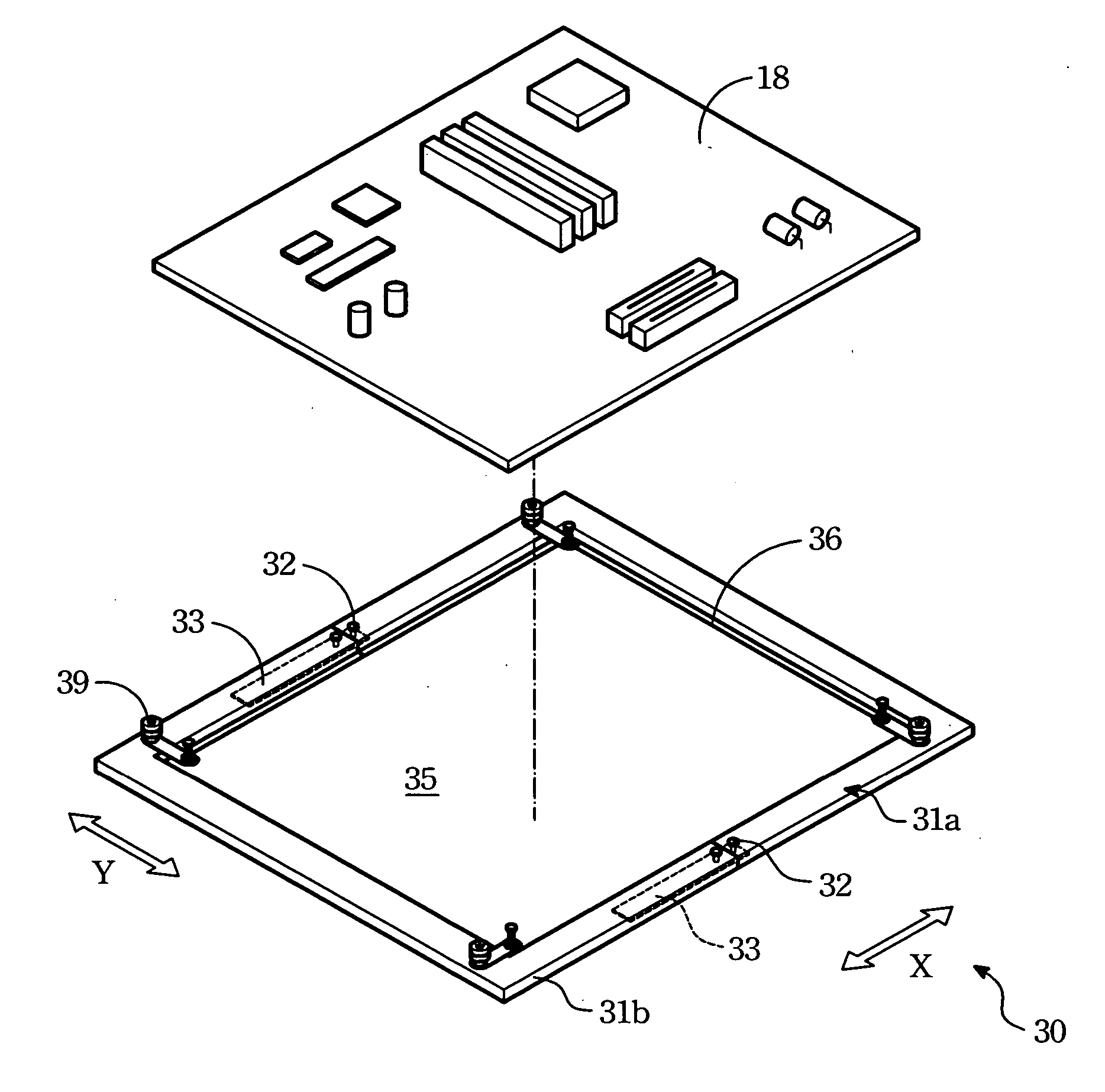
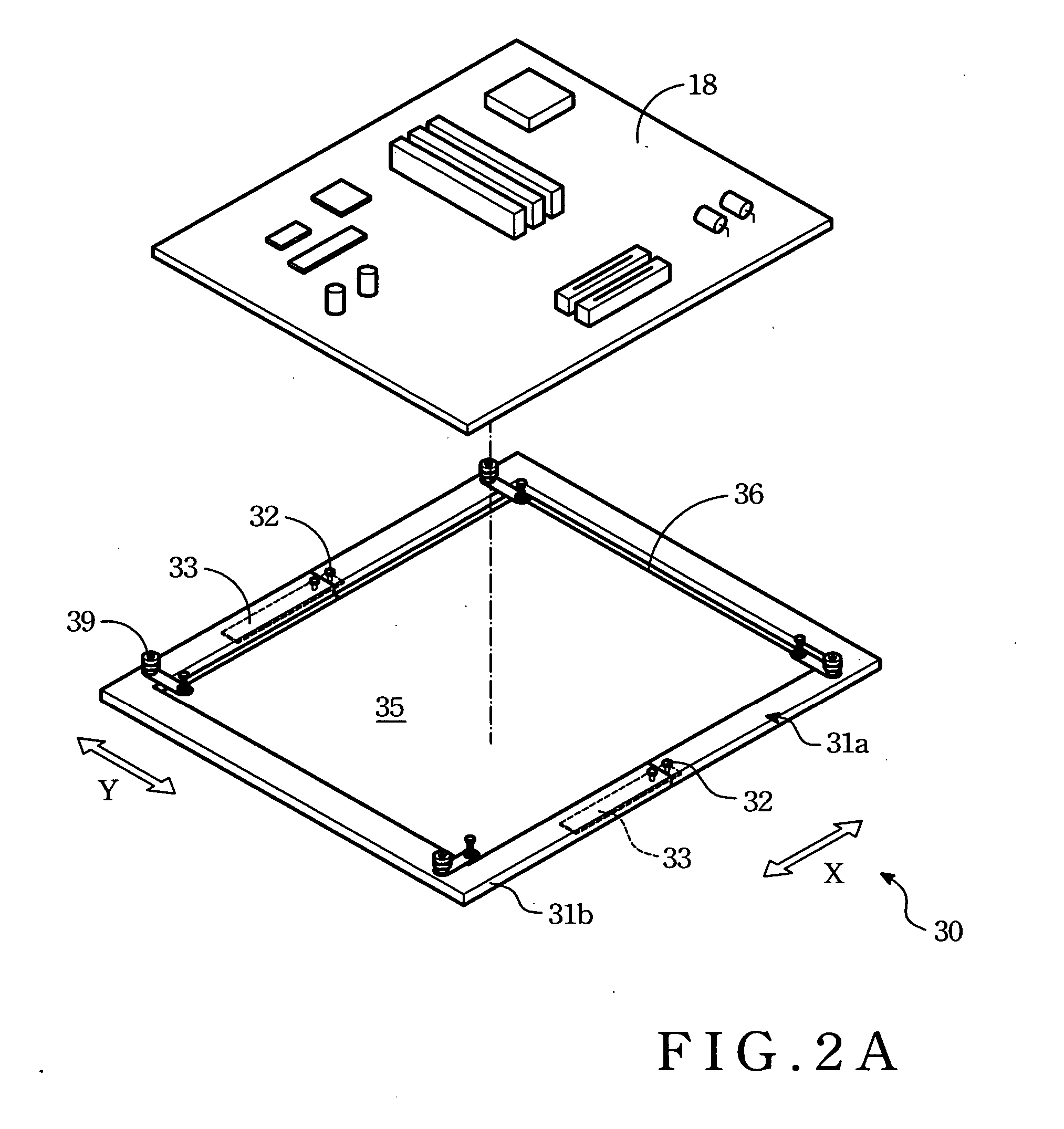
[0017] Refer to FIGS. 2A, 2B and 2C for the adjustable frame fixture 30. It includes two side frames 31, two fasteners 32 and two coupling members 33.
[0018] The side frames 31 may be formed in reversed U-shape or L-shape to couple with each other to form a holding dock 35 to hold a PCB 18. The side frames 31 have anchor holes 313. The fasteners 32 run through the anchor holes 313 to couple and fasten the neighboring side frames 31a and 31b.
[0019] The two coupling members 33 are located between the two neighboring side frames 31a and 31b for connecting and fastening the two. Each of the coupling members 33 has a second anchor hole 314. One fastener 32 may run through the second anchor hole 314 to connect and fasten the two neighboring side frames 31a and 31b.
[0020] By adjusting the positions of the two neighboring side frames 31a and 31b, the frame fixture 30 may be formed with a holding area of different sizes. And the side frames 31 may be anchored through the fasteners 32 to hol...
second embodiment
[0022] Refer to FIG. 3A for the invention. The first embodiment depicted above provides dimension adjustment for only one direction (such as X direction), but cannot be adopted to two-direction adjustment. The second embodiment aims to provide a two-direction adjustable frame fixture 30. It has four side frames 31, eight fasteners 32 and four coupling members 33. The side frames 31 may be formed in L-shape or I-shape. The structure and function of the fasteners 32 and coupling members 33 are same as the first embodiment. Details are omitted.
[0023] Refer to FIG. 3B for the cross section of two neighboring side frames according to the invention in a coupling condition. By means of the constructions set forth above, the frame fixture can provide dimension adjustment in two directions to hold the PCB of different sizes. It provides improved adaptability and applicability.
third embodiment
[0024] Refer to FIGS. 4A and 4B for the invention. It aims at a PCB 18 with SMT elements 181 on the back side. The two previous embodiments are designed for the PCB without a back soldering plate. Hence when DIP elements 182 undergo wave soldering process, the SMT elements 181 will be damaged.
[0025] This embodiment provides an adjustable frame fixture 30 with a back soldering plate 40. The back soldering plate 40 has carved out openings 41 and masks 42 formed on the surface. The masks 42 are used to cover the SMT elements 181 of the PCB 18. The pins of the DIP element 182 are exposed to the openings 41. The other elements include side frames 31, fasteners 32 and coupling members 33, and are same as the previous embodiments. Details are omitted.
[0026] The adjustable frame fixture according to the invention may be adapted to PCBs of different specifications. Thus whatever design changes happened to the PCB specifications, the frame fixture of the invention is applicable without obsol...
PUM
| Property | Measurement | Unit |
|---|---|---|
| Time | aaaaa | aaaaa |
| Size | aaaaa | aaaaa |
| Shape | aaaaa | aaaaa |
Abstract
Description
Claims
Application Information