Wing gull integration nacelle clearance, compact landing gear stowage, and sonic boom reduction

a technology of integration nacelle and compact landing gear, which is applied in the direction of canard-type aircraft, aircraft navigation control, transportation and packaging, etc., can solve the problems of negative response and regulatory limitations on supersonic travel, difficult to design an aircraft with an n-wave signature of sufficiently low amplitude, and difficult to achieve the effect of facilitating the appropriate tail clearan

Active Publication Date: 2005-03-31
SUPERSONIC AEROSPACE INT
View PDF17 Cites 19 Cited by
  • Summary
  • Abstract
  • Description
  • Claims
  • Application Information

AI Technical Summary

Benefits of technology

[0009] What is desired is a supersonic aircraft with appropriate tail clearance for takeoff and landing and a landing gear configuration that facilitates the appropriate tail clearance while stowing in a compact arrangement.
[0011] According to other embodiments, an aircraft comprises a fuselage extending on a longitudinal axis from a forward nose to an aft tail, a wing coupled at an inboard section to the fuselage and extending to an outboard tip, and having a leading edge and a trailing edge, a leading edge flap coupled to the leading edge of the wing, and a landing gear. The landing gear is coupled to the wing and capable of stowing into the wing and fuselage on retraction. The landing gear stows within the wing at a selected chordwise location between the wing leading and trailing edges. The wing has an inboard dihedral that is straight near the leading edge and angled at the chordwise location of the landing gear to facilitate leading edge flap deployment and sealing.

Problems solved by technology

Supersonic flight over the United States and other countries is a challenging environmental issue for a viable supersonic commercial aircraft.
Previous research has shown that the highly impulsive nature of the “N-wave” sonic-boom signatures of all existing supersonic aircraft is the primary cause of negative response and regulatory limitations on supersonic travel.
Conclusions of NASA research further indicate the exceptional difficultly of designing an aircraft with an “N-wave” signature of sufficiently low amplitude for general public acceptance.
However, for a plane flying at supersonic speeds, the air cannot easily flow around the plane and is instead compressed, generating a pressure pulse through the atmosphere.

Method used


Image

  • Wing gull integration nacelle clearance, compact landing gear stowage, and sonic boom reduction
  • Wing gull integration nacelle clearance, compact landing gear stowage, and sonic boom reduction
  • Wing gull integration nacelle clearance, compact landing gear stowage, and sonic boom reduction

Examples


Embodiment Construction

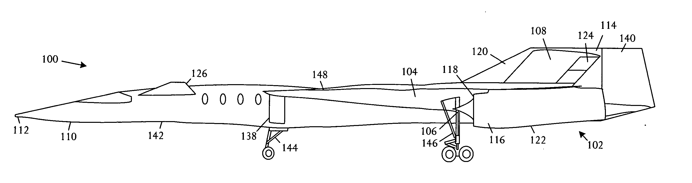
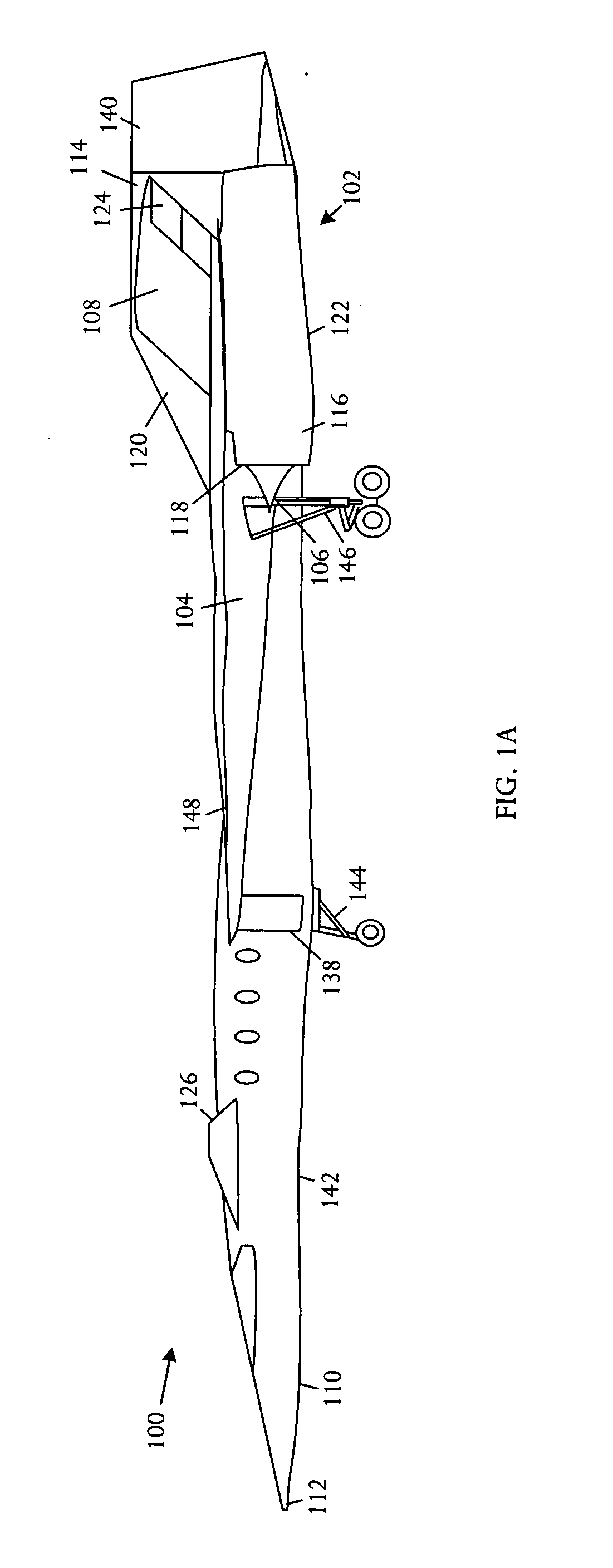
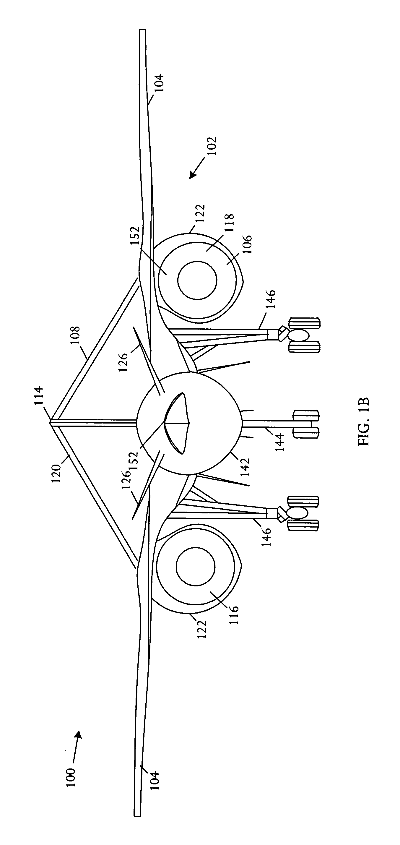
[0020] Referring to FIGS. 1A, 1B, and 1C, schematic pictorial diagrams respectively showing side, front, and top views of a supersonic cruise configuration aircraft 100 comprising a fuselage 142 extending on a longitudinal axis from a forward nose 110 to an aft tail 114. A wing 104 is coupled at an inboard section to the fuselage 142 and extends to an outboard tip, and has a leading edge and a trailing edge. The aircraft 100 further comprises a landing gear 146 that is coupled to the wing 104 and can of stowing into the wing 104 and fuselage 142 on retraction. The landing gear 146 has a landing gear strut. The wing 104 is gulled with a dihedral at an angle that is increased inboard and aligns with the retracted landing gear 146. The wing 104 has a minimum thickness sufficient to enclose the landing gear 146.

[0021] In some embodiments, the aircraft 100 further comprises a leading edge flap 134, for example a Krueger flap, which is coupled to the leading edge of the wing 104. The lea...


PUM


Abstract

A supersonic cruise configuration aircraft comprises a fuselage extending on a longitudinal axis from a forward nose to an aft tail, and a wing coupled at an inboard section to the fuselage and extending to an outboard tip, and having a leading edge and a trailing edge. The aircraft further comprises a landing gear that is coupled to the wing and capable of stowing into the wing and fuselage on retraction. The landing gear has a landing gear strut. The wing is gulled with a dihedral at an angle that is increased inboard and aligns with the retracted landing gear. The wing has a minimum thickness sufficient to enclose the landing gear.

Description

BACKGROUND OF THE INVENTION [0001] Supersonic flight over the United States and other countries is a challenging environmental issue for a viable supersonic commercial aircraft. Current FAA regulations prohibit civil flights at Mach numbers greater than one without case-by-case exceptions approved by the Administrator. Many other countries have similar restrictions. [0002] Previous research has shown that the highly impulsive nature of the “N-wave” sonic-boom signatures of all existing supersonic aircraft is the primary cause of negative response and regulatory limitations on supersonic travel. Conclusions of NASA research further indicate the exceptional difficultly of designing an aircraft with an “N-wave” signature of sufficiently low amplitude for general public acceptance. However, the research also found that a “shaped” signature was less objectionable and that a reasonably achievable amplitude wave could meet Committee on Hearing and Bioacoustics of the National Research Coun...

Claims


Application Information

Patent Timeline
Patent Type & Authority Applications(United States)
IPC IPC(8): B64C1/00B64C3/10B64C3/16B64C9/24B64C25/10B64C30/00B64C39/12B64D27/18
CPCB64C1/0009B64C3/10B64C3/16B64C9/24B64C25/10B64C30/00B64C39/12B64C2001/0045B64D27/18Y02T50/10Y02T50/30Y02T50/40
Inventor QUAYLE, BRIANMORGENSTERN, JOHNARSLAN, ALAN
Owner SUPERSONIC AEROSPACE INT
Why Eureka
Try Eureka