Rotorcraft having coaxial counter-rotating rotors which produce both vertical and horizontal thrust and method of controlled flight in all six degrees of freedom

a rotorcraft and rotor blade technology, applied in the field of helicopters, vertical takeoff and landing aircraft, can solve the problems of lack of controllability, complex control mechanism required to change the pitch of the main rotor blade, and no prior art helicopters, rotorcrafts and aircraft are capable of fligh

Inactive Publication Date: 2005-03-31
PETERSEN BRUCE L
View PDF8 Cites 96 Cited by
  • Summary
  • Abstract
  • Description
  • Claims
  • Application Information

AI Technical Summary

Benefits of technology

[0015] The present invention is a rotorcraft which provides controlled flight in all six degrees of freedom, a rotor system for rotorcraft, and a method for providing flight for rotorcraft.
[0016] The rotorcraft includes a fuselage and at least two rotor blade assemblies rotatably mounted to the fuselage about a vertically disposed central axis. Each rotor blade assembly has a plurality of radially-extending airfoil shaped blades adapted to produce variable vertical and horizontal thrust components during operation. A rotor drive system is mounted to the fuselage which includes a power device adapted for rotationally driving the rotor blade assemblies in opposite rotational directions. A rotor blade control system operatively connected to the blades adapted to control the vertical and horizontal thrust components of the blades of the rotor blade assemblies. The rotor blade control system includes a controller adapted to monitor the rotational location of each blade relative to the fuselage and input signals indicative of required vertical and horizontal thrust components of each blade to blade control devices adapted to change said vertical and horizontal thrust components of said blades throughout each revolution of each blade about the fusela

Problems solved by technology

The major problem with the prior art helicopters, rotorcrafts, and other aircraft is the lack of controllability.
None of the prior art helicopters, rotorcrafts, and aircraft are capable of flight in all six degrees of freedom or combinations thereof.
There are a number of other problems with the prior art helicopters, rotorcrafts, and other aircraft, depending on the particular type of craft involved.
For example, in helicopters and some rotorcraft the pitch control mechanism required to change the pitch of the main rotor blades is very complex and prone to mechanical failure, and excessive stresses are sometimes placed on the main rotor shaft, the pitch control mechanism, and the rotor blades during flight maneuvers which is also a

Method used


Image

  • Rotorcraft having coaxial counter-rotating rotors which produce both vertical and horizontal thrust and method of controlled flight in all six degrees of freedom
  • Rotorcraft having coaxial counter-rotating rotors which produce both vertical and horizontal thrust and method of controlled flight in all six degrees of freedom
  • Rotorcraft having coaxial counter-rotating rotors which produce both vertical and horizontal thrust and method of controlled flight in all six degrees of freedom

Examples


first embodiment

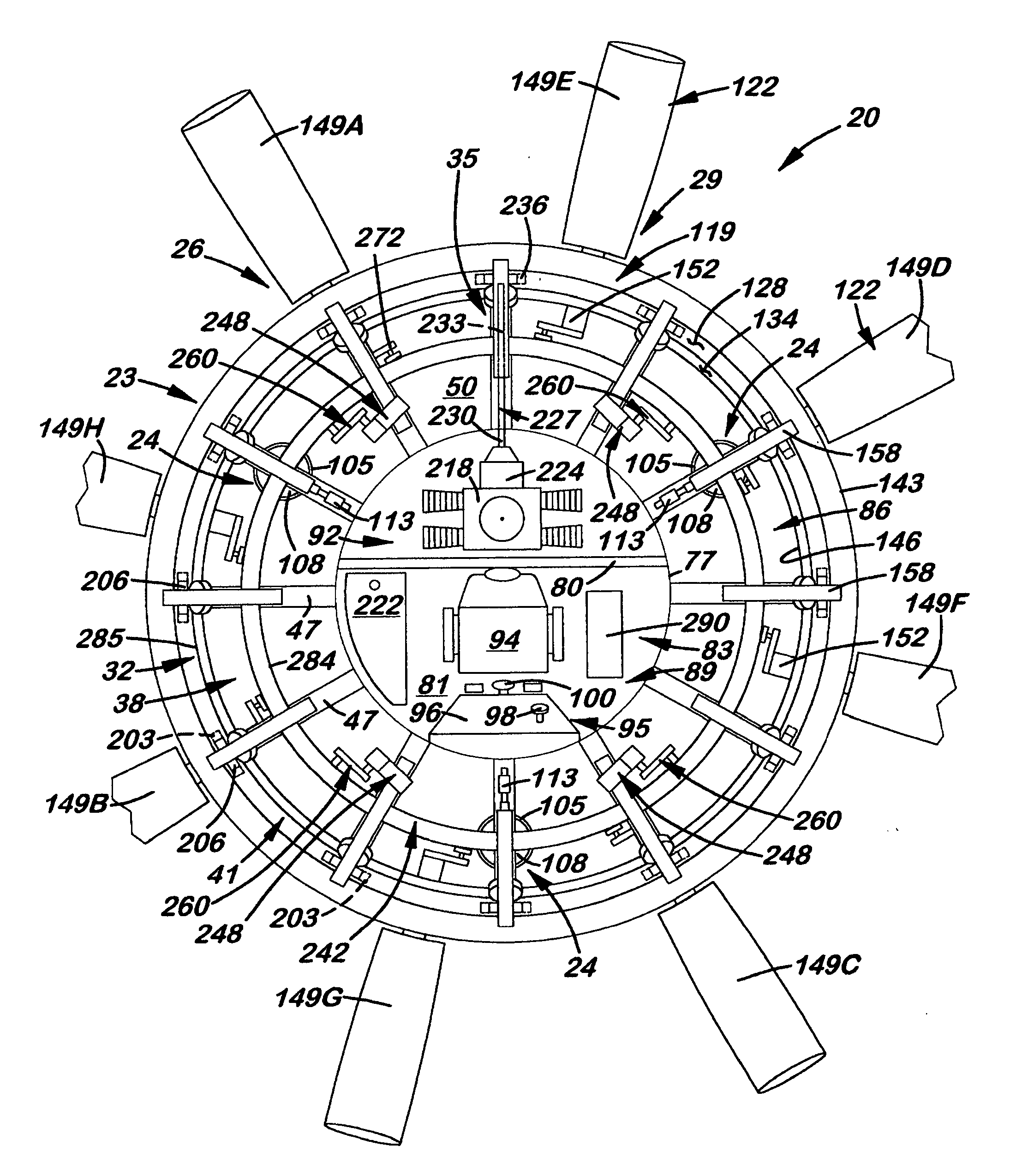
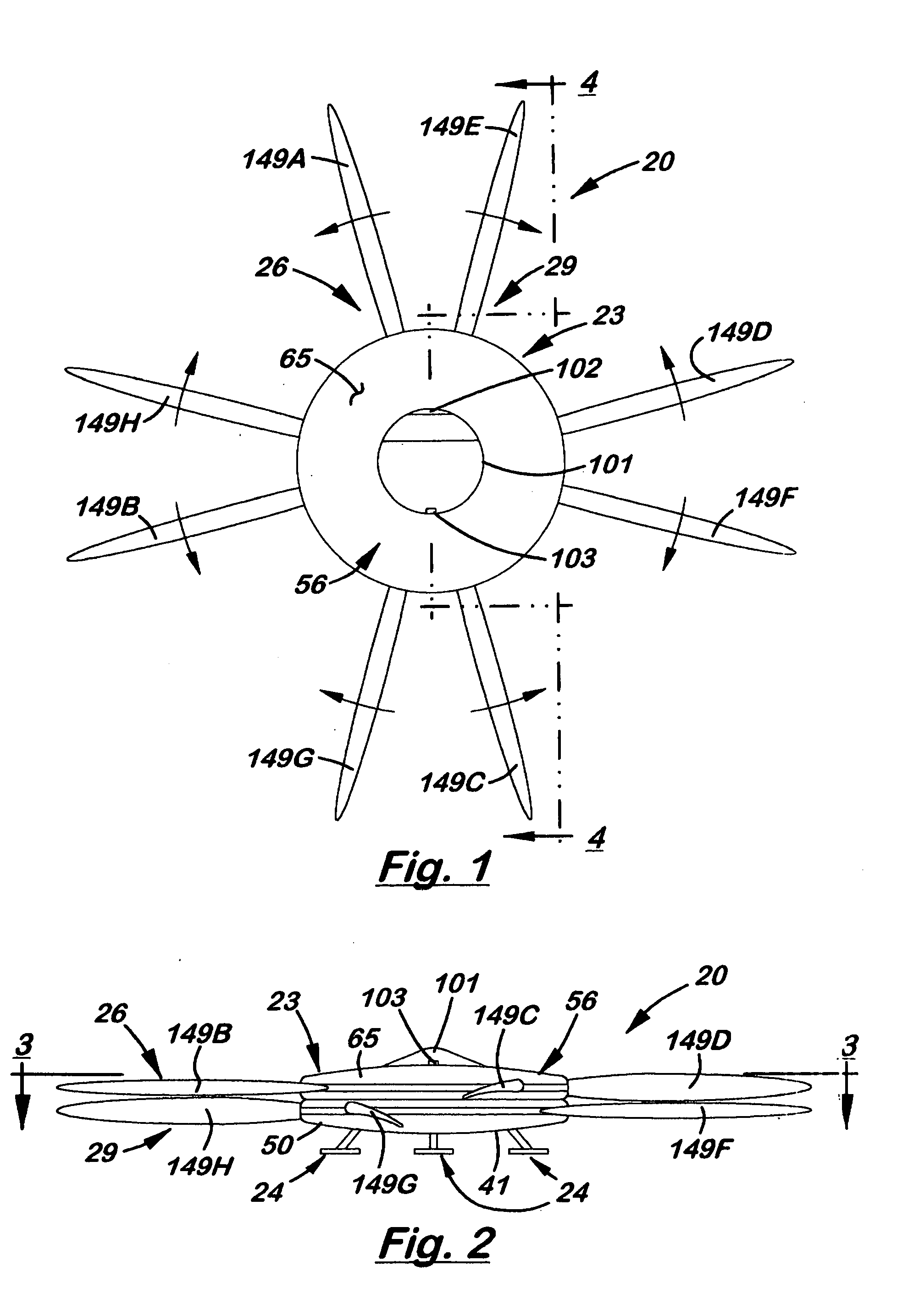
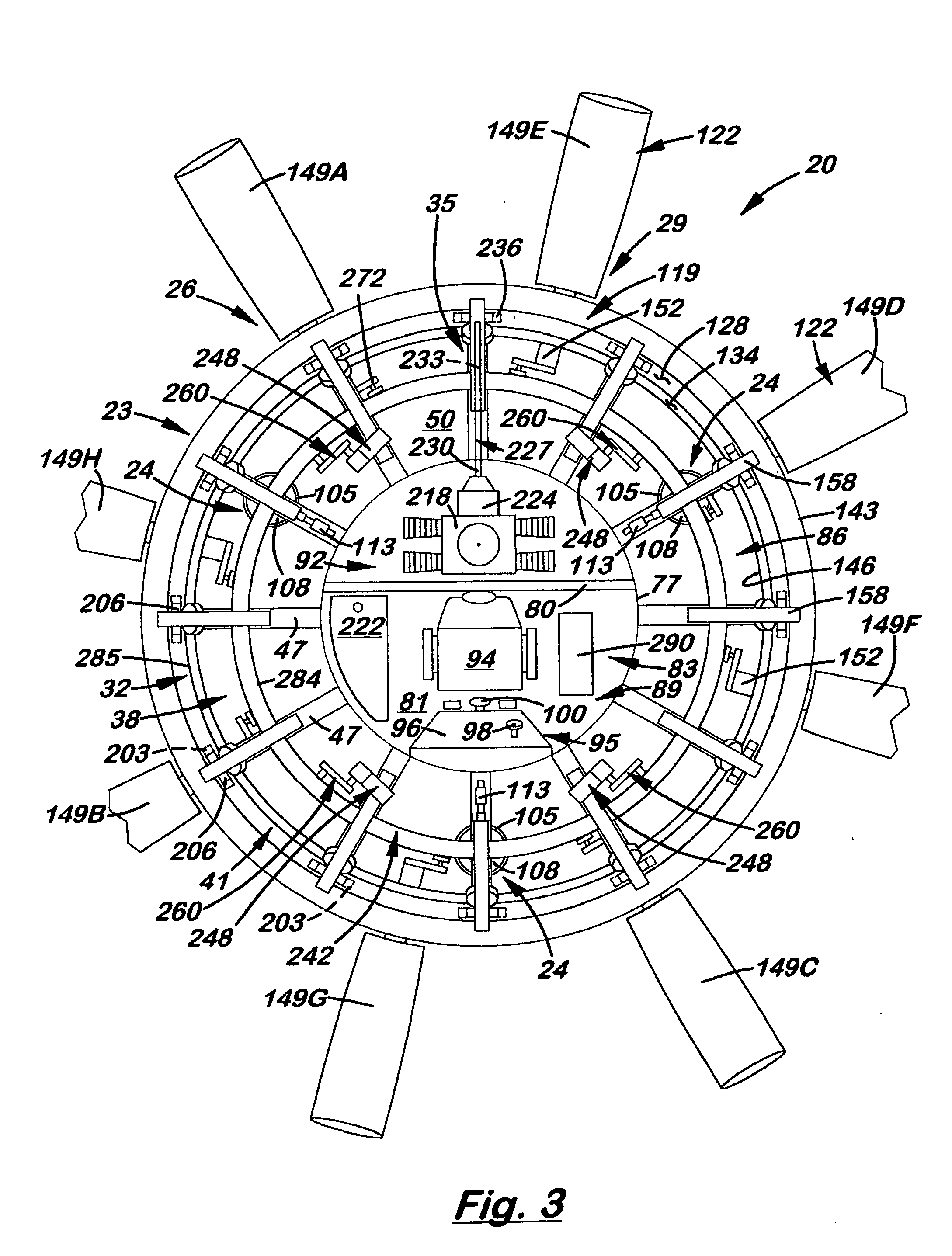
[0055] Referring to FIGS. 1-6, therein is shown a first embodiment rotorcraft in accordance with the present invention which provides controlled flight in all six degrees of freedom, designated generally at 20. The rotorcraft 20 includes a fuselage 23, a plurality of landing gear 24, and a rotor system comprised of a pair of counter-rotating upper and lower rotor blade assemblies 26 and 29, a rotor support assembly 32, a rotor drive system 35, and a rotor blade pitch control system 38.

[0056] The fuselage 23 shown is of a substantially circular shape as viewed from above and below, though other configurations are possible including elongate versions having multiple pairs of rotor blade assemblies 26 and 29 which are longitudinally or laterally spaced thereon. The fuselage 23 includes a circular lower frame 41 comprised of a lower annular frame 44 from which a plurality of radially-extending tapered floor beams 47 of an I-beam cross-section extend covered by a lower skin 50. The annul...

second embodiment

[0100] The precise individual control of the vertical and horizontal thrust components of each blade 149 (even more independently controllable in the second embodiment following) allows the pilot of the rotorcraft 20 to compensate for turbulence, and varying wind conditions such as wind gusts. For example, if a prevailing wind is present prior to take-off which could lift the upwind side of the rotorcraft 20 during take-off and possibly flipping over the rotorcraft 20, a small amount of negative pitch angle my be applied to the blades 149A-D and E-H passing through the upwind of sector of the rotorcraft 20 prior to take-off while warming up the engine 218 to keep the rotorcraft 20 firmly on the ground. Upon lift-off and flight of the rotorcraft 20, positive and negative pitch angles may be utilized to compensate for prevailing wind, wind gusts, and any other undesired wind interference regardless of the speed, direction, attitude, or proximity to obstacles encountered during flight....

third embodiment

[0107] Referring to FIGS. 29-34, therein is shown a third embodiment rotorcraft 329 in accordance with the present invention which provides controlled flight in all six degrees of freedom. The rotorcraft 329 comprises the circular fuselage 23, the plurality of landing gear 24, a pair of counter-rotating rotor blade assemblies 332 and 335, the rotor support assembly 32, the rotor drive system 35, and a rotor blade pitch control system 338 which is the same as rotor blade pitch control system 38 except for a different controller in the form of a computer 341, and thus not further explained.

[0108] The rotor blade assemblies 332 and 335 each include a pair of the gear rings 119 and a plurality of blade assemblies 344. The rotor blade assemblies 344 each include a plurality of radially-extending airfoil shaped blades 347 fixedly mounted to the gear rings 125 at a fixed pitch about the respective longitudinal axes. The blades 247 are similar to blades 149 but with a flap slot 350 and resp...


PUM


Abstract

A rotorcraft and method for providing controlled flight which provides flight in all six degrees of freedom of pitch, roll, yaw, up/down, forward/rear, and left/right. The rotorcraft includes a fuselage with a pair of counter-rotating rotor blade assemblies each having a plurality of radially-extending airfoil shaped blades about a vertically disposed central axis. A rotor drive system mounted to the fuselage includes a motor or engine for rotationally driving the rotor blade assemblies. A rotor blade control system monitors the rotational location of each blade relative to the fuselage and allows a pilot to control respective vertical and horizontal thrust components of the blades corresponding to lift versus drag characteristics of the airfoils during rotation about the fuselage. This is done by changing the pitch angles of the blades and/or by utilizing respective flaps pivotally mounted to the blades to change the effective pitch angle of the blades.

Description

BACKGROUND OF THE INVENTION [0001] 1. Field [0002] The present invention relates generally to helicopters, vertical take-off and landing (VTOL) aircraft, and other rotorcraft which utilize horizontally disposed rotors to provide lift, and more specifically to such rotorcraft which utilize pairs of counter-rotating rotors to offset engine torque rather than a vertically disposed tail rotor. [0003] 2. State of the Art [0004] Helicopters, VTOL aircraft, and other rotorcraft which are capable of vertical take-offs and landings are well known in the prior art. Extensive research and development has particularly been conducted particularly regarding helicopters over the last few decades. Advances in the area of drive systems, rotors, aerodynamics, and the like have made the helicopters a reliable form of transportation particularly used in the various branches of the military and the Coast Guard. [0005] Conventional helicopters develop lift or vertical thrust during flight by continuously...

Claims


Application Information

Patent Timeline
IPC IPC(8): B64C27/10B64C27/605B64C27/615B64C39/00
CPCB64C27/10B64C27/605Y02T50/34B64C39/001B64C27/615B64C27/20B64C27/56Y02T50/30B64C27/08
Inventor PETERSEN, BRUCE L.
Owner PETERSEN BRUCE L
Why Eureka
Try Eureka