Optically addressed extreme ultraviolet modulator and lithography system incorporating modulator

a modulator and ultraviolet technology, applied in the field of modulators, can solve the problems of small motions that cannot impress significant phase changes on reflected visible or ultraviolet, and achieve the effects of high coefficient of thermal expansion, and rapid spatial addressing of modulators

Inactive Publication Date: 2005-03-31
PUREX
View PDF24 Cites 6 Cited by
  • Summary
  • Abstract
  • Description
  • Claims
  • Application Information

AI Technical Summary

Benefits of technology

[0006] The present invention provides very rapid spatial addressing of a modulator without requiring a matrix of addressing wires and associated switching circuits. Instead, a desired spatial pattern is imprinted on the modulator by an optical beam. The modulator includes multilayer mirrors that reflect with changed amplitude and / or phase when subjected to a temperature impulse. The imprinting optical beam supplies a spatial pattern that is absorbed in the modulator structure, becoming a thermal pattern. The modulator structure contains at least one layer of optically absorbing material with a high coefficient of thermal expansion. In regions of high optical intensity, this layer expands, modifying the amplitude and / or phase of EUV or soft X-ray radiation reflected by the modulator structure in such regions.
[0007] The modulator of the present invention is passive, in the sense that no electric power is required to drive the modulator, and does not require micro-lenses. The thermal expansion principle is much more effective for the modulation of extreme ultraviolet or soft X-ray radiation because in these regions of the spectrum significant phase changes only require motions of the order of one nanometer, which are readily achieved in materials of high thermal expansion coefficient with temperature excursions as small as a few tens of degrees Centigrade. Such small motions are not able to impress significant phase changes on reflected visible or ultraviolet light.
[0008] According to a first aspect of the invention, a modulator for extreme ultraviolet or soft X-ray radiation comprises a modulator structure that is reflective of extreme ultraviolet or soft X-ray radiation, said modulator structure including material having a high coefficient of thermal expansion, wherein said modulator structure expands in response to illumination with a light beam and alters a parameter of reflected extreme ultraviolet or soft X-ray radiation.
[0009] In some embodiments, the modulator structure comprises a multilayer mirror and the material having a high coefficient of thermal expansion comprises one or more layers of the multilayer mirror. In other embodiments, the modulator includes a substrate and the modulator structure comprises a multilayer mirror and a layer of the material having a high coefficient of thermal expansion between the multilayer mirror and the substrate. The modulator structure may be configured to modulate the amplitude and / or the phase of the reflected extreme ultraviolet or soft X-ray radiation. In further embodiments, the modulator includes a substrate and the modulator structure comprises an array of individual modulator elements affixed to the substrate. The modulator structure may be configured to produce a thermal pattern in response to a light beam having a spatial intensity pattern.
[0010] According to a second aspect of the invention, a lithography system is provided. The lithography system comprises a modulator for extreme ultraviolet or soft X-ray radiation, including a modulator structure that is reflective of extreme ultraviolet or soft X-ray radiation, said modulator structure including a material having a high coefficient of thermal expansion; an optical pattern generator configured to project a light beam carrying a spatial intensity pattern onto the modulator to produce a thermal pattern in the modulator; a photon source configured to illuminate the modulator with extreme ultraviolet or soft X-ray radiation; and a projection assembly configured to image onto a target extreme ultraviolet or soft X-ray radiation reflected from the modulator and modulated in response to the thermal pattern.

Problems solved by technology

Such small motions are not able to impress significant phase changes on reflected visible or ultraviolet light.

Method used


Image

  • Optically addressed extreme ultraviolet modulator and lithography system incorporating modulator
  • Optically addressed extreme ultraviolet modulator and lithography system incorporating modulator
  • Optically addressed extreme ultraviolet modulator and lithography system incorporating modulator

Examples


Embodiment Construction

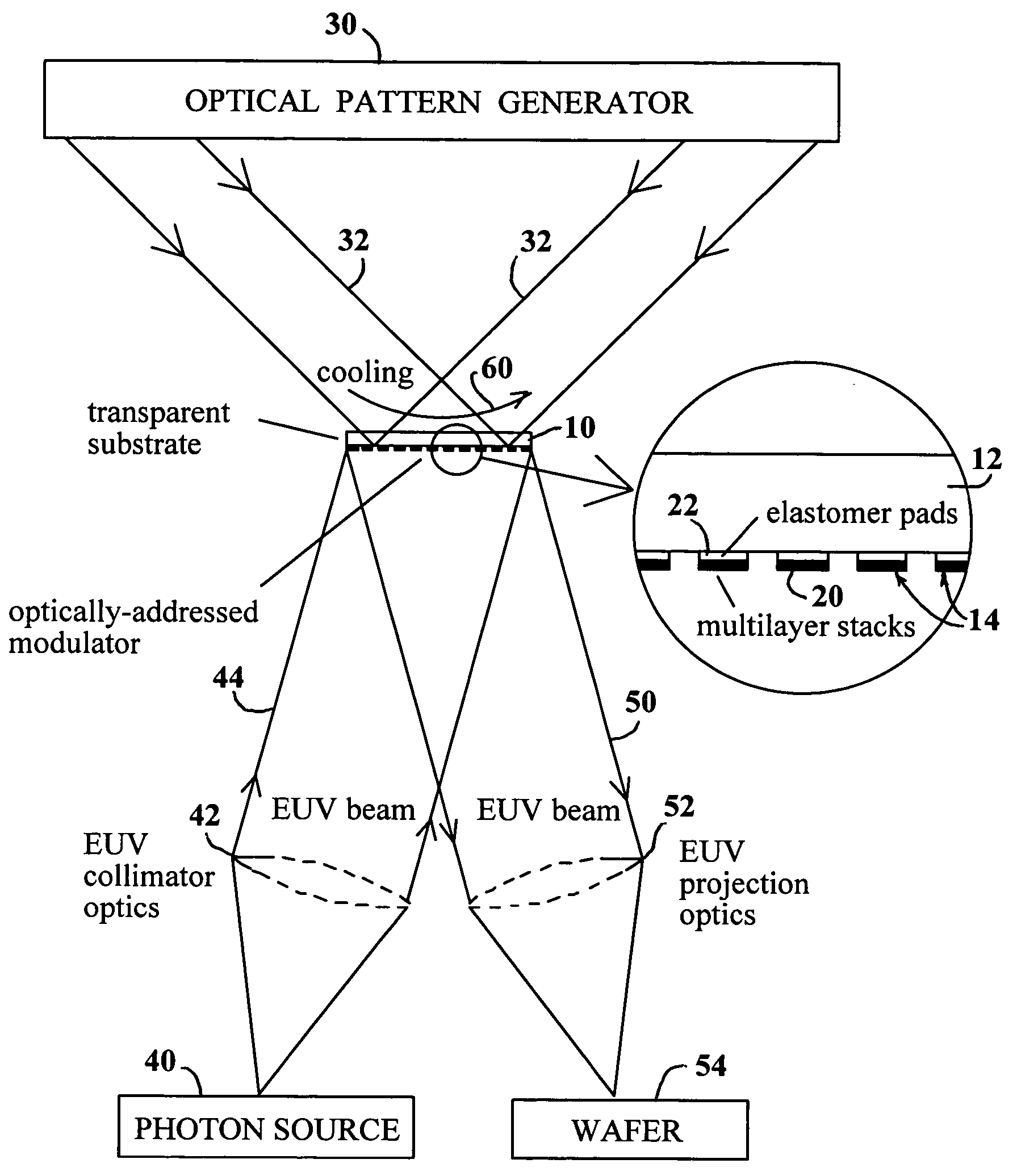
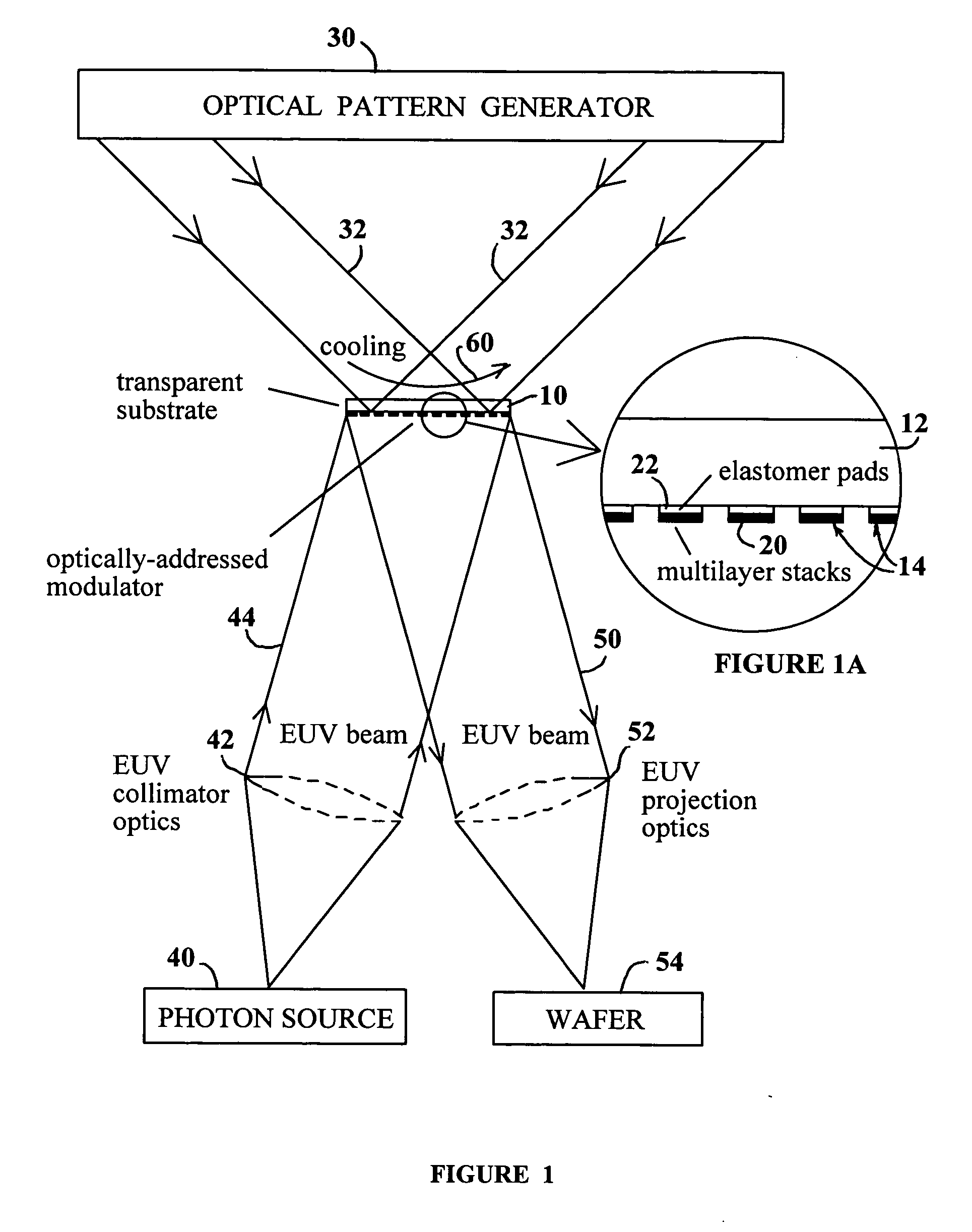
[0021] A schematic block diagram of a lithography system in accordance with the first embodiment of the invention is shown in FIGS. 1 and 1A. A modulator 10 is configured for optical patterning and for reflection of extreme ultraviolet or soft X-ray radiation. While the discussion herein refers to EUV operation, it will be understood that the present invention is applicable to extreme ultraviolet and soft X-ray radiation, typically in a wavelength range of 1 to 100 nm (nanometers).

[0022] In the embodiment of FIGS. 1 and 1A, modulator 10 includes a light-transmissive substrate 12 and an array of modulator elements 14 affixed to substrate 12. Modulator elements 14 may be arranged in rows and columns and may define pixels of a pattern. Each of the modulator elements 14 may include a multilayer mirror 20 and a thermally expandable pad or layer 22 of a material having a high coefficient of thermal expansion. Other embodiments of modulator 10 are described below.

[0023] An optical patter...


PUM

PropertyMeasurementUnit
wavelength rangeaaaaaaaaaa
feature sizesaaaaaaaaaa

Abstract

An optically addressed extreme ultraviolet (EUV) modulator in which a spatial amplitude or phase pattern is provided to an EUV beam that is reflected from, or transmitted through the modulator. The modulator includes a modulator structure that includes a material with a high coefficient of thermal expansion. When a thermal impulse is incident on one part of the modulator, the resulting expansion changes the reflected phase or amplitude of the EUV beam from that part. A thermal pattern is imprinted on the modulator by absorption of a visible or ultraviolet pattern, resulting in a corresponding modulation of the EUV beam. A lithography system is based on the optically addressed EUV modulator.

Description

CROSS-REFERENCE TO RELATED APPLICATION [0001] This application claims the benefit of provisional application Ser. No. 60 / 497,204, filed Aug. 22, 2003, which is hereby incorporated by reference in its entirety.FIELD OF THE INVENTION [0002] This invention relates to a modulator for extreme ultraviolet or soft X-ray radiation. The modulator is particularly useful in lithography systems, but is not limited to lithography applications. BACKGROUND OF THE INVENTION [0003] The process of maskless lithography using photons, as disclosed in U.S. Pat. No. 5,691,541, issued Nov. 25, 1997 to Ceglio and Markle, utilizes a “programmable array of binary light switches” that generates a spatially modulated light field. The modulated light field is then relayed optically to the surface of a substrate that receives the desired circuit pattern. Ceglio and Markle discuss the use of extreme ultraviolet (EUV) light and a digital micro-mirror array in which the pixels comprise individual EUV mirrors that a...

Claims


Application Information

Patent Timeline
Patent Type & Authority Applications(United States)
IPC IPC(8): G02F1/07G03F7/20
CPCG03F7/7045G03F7/70291
Inventor MCGEOCH, MALCOLM W.
Owner PUREX
Why Eureka
Try Eureka