Modular LED light and method

a module-type, led light technology, applied in the direction of lighting applications, light source combinations, lighting, etc., can solve the problems of less than optimal efficiency of bulb-type devices, limited energy available, and large heat dissipation of bulb-type devices, and achieve simple, inexpensive and aesthetically pleasing manners. , the effect of simple housing configuration

Inactive Publication Date: 2005-03-31
J W SPEAKER CORP
View PDF60 Cites 96 Cited by
  • Summary
  • Abstract
  • Description
  • Claims
  • Application Information

AI Technical Summary

Benefits of technology

[0021] It has been recognized that simple light modules can be configured that direct almost all light emitted by a light emitter radially through a light guide and that the intensity of the resulting light can be sufficient in some cases to meet SAE intensity standards for flashing lights. It has also been recognized that, even in cases where a specific SAE standard cannot be met with a single light emitter module, two or more modules can be stacked together to, in combination, generate enough light to meet SAE standards. Moreover, it has been recognized that a simple housing configuration can be used to hold modules together in a stacked fashion in a simple, inexpensive and aesthetically pleasing manner. Furthermore, it has been recognized that electrical leads to provide currents to the modules can be staggered angularly about a central axis of the modules to avoid problems associated with staging modules and to therefore provide strobe type lights where light intensity is essentially uniform from all angels about the light assembly.

Problems solved by technology

First, in addition to generating light, bulb type devices also generate a relatively large quantum of heat which is dissipated as wasted energy.
Thus, bulb type devices are less than optimally efficient.
While inefficient bulb type devices are suitable for some applications where energy is effectively inexhaustible, in other applications energy available is limited and device efficiency is important.
In these cases the energy source is limited and efficient energy use is particularly important.
Second, some bulb type devices (e.g., xenon bulbs) produce significant electromagnetic interference (“EMI”).
As well known in the electronics industry, EMI disturbs proximate electronics in both the strobe light and other electronics proximate the light.
In fact, EMI emissions have become so troublesome in some applications that many municipalities now regulate EMI emission levels from strobe lights and other types of electronic devices.
Where expected EMI emissions from a bulb are potentially high, strobe lights have to be designed to shield the emissions from emanating from the light structure which increases overall light costs.
Third, the useful life of an incandescent bulb or a xenon bulb is relatively short (i.e., the bulbs burn out) and the bulbs routinely have to be replaced.
Replacement is costly in terms of materials as well as maintenance time and, in many cases, downtime as a vehicle operator on which a bulb burns out may have to halt work and replace the bulb to conform to safety requirements.
Exacerbating matters further, the useful life of a bulb is usually shorted when a bulb type device is mounted to a vehicle, a machine, or the like that vibrates during use.
Here, the vibrations have been known to degrade filament integrity expeditiously.
Fourth, because bulbs have to be routinely replaced on bulb type devices, the bulb type devices have to be designed so that the housing can be dis-assembled to facilitate replacement.
The disassembly requirement increases costs generally and, in addition, results in a lighting configuration where it is relatively difficult to form a complete hermetic seal about the bulb and the driving electronics.
While an elastomeric sealing ring or the like can be provided to help overcome this limitation, the ring represents additional cost and, if aligned improperly during assembly or maintenance, can result in a semi-exposed bulb which can further expedite bulb (and electronics) deterioration.
Fifth, most bulb type devices are designed for specific purposes and their components cannot be swapped out easily to configure lighting devices useable for other applications.
Separate components for each lighting requirement increases the costs of providing any one of the bulb type devices as device components cannot be standardized among devices.
In this regard, LEDs consume considerably less power than light bulbs, produce essentially no EMI and, in many cases, have an essentially infinite useful life such that they do not have to be replaced.
Unfortunately, typical LEDs have a lighting pattern that does not emit enough light radially to meet SAE requirements.
While LED type devices solve some of the problems associated with bulb type devices, unfortunately, LED type devices also have shortcomings.
To this end, as with most products, in the case of an LED type lighting device, increased parts count to provide an array of LEDs and support structure increases device costs appreciably.
In addition, as parts count increases, assembly costs also increase and the likelihood of faulty assembly is increased.
Furthermore, as more power is consumed, the LEDs generate more heat and special heat dissipating structures are required which further increases costs and limits array arrangements (i.e., limits how closely LEDs can be packed together to provide required illumination).
While the '911 patent device described above radially disperses a greater percentage of generated light and uses less power than other known LED type devices, even this device falls short of optimal operating characteristics.
Thus, while the 70% number taught in the '911 patent is assumed above, even this number is questionable.
In addition, 50% of the light generated by most LEDs and spread out over 360 degrees will not meet even the lowest SAE light emitting requirements.
Thus, while the '911 patent device may be suitable for road lane marking, unless a relatively expensive and high power LED is employed, such a device may not be useful for strobe light applications.

Method used


Image

  • Modular LED light and method
  • Modular LED light and method
  • Modular LED light and method

Examples


Embodiment Construction

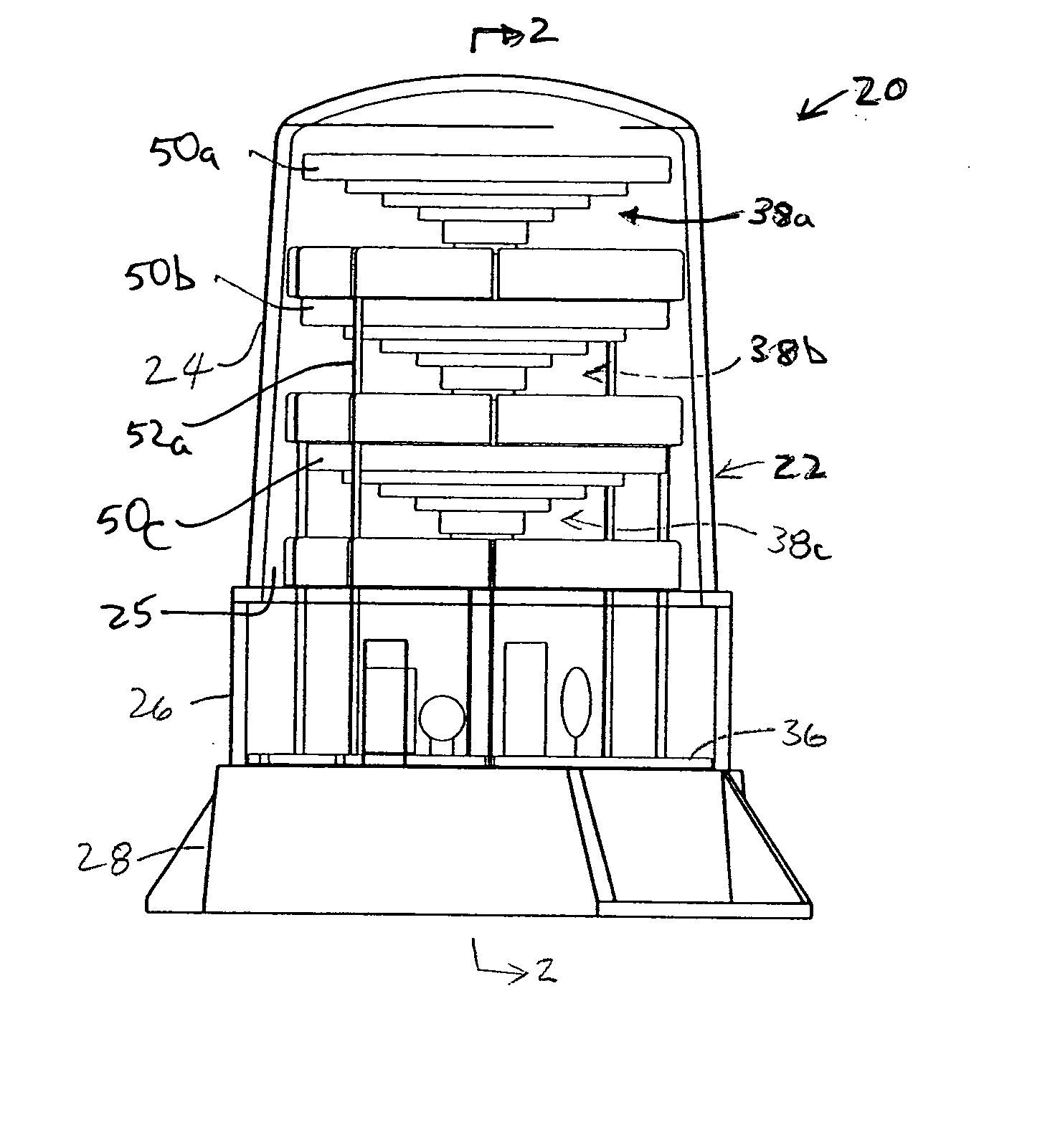
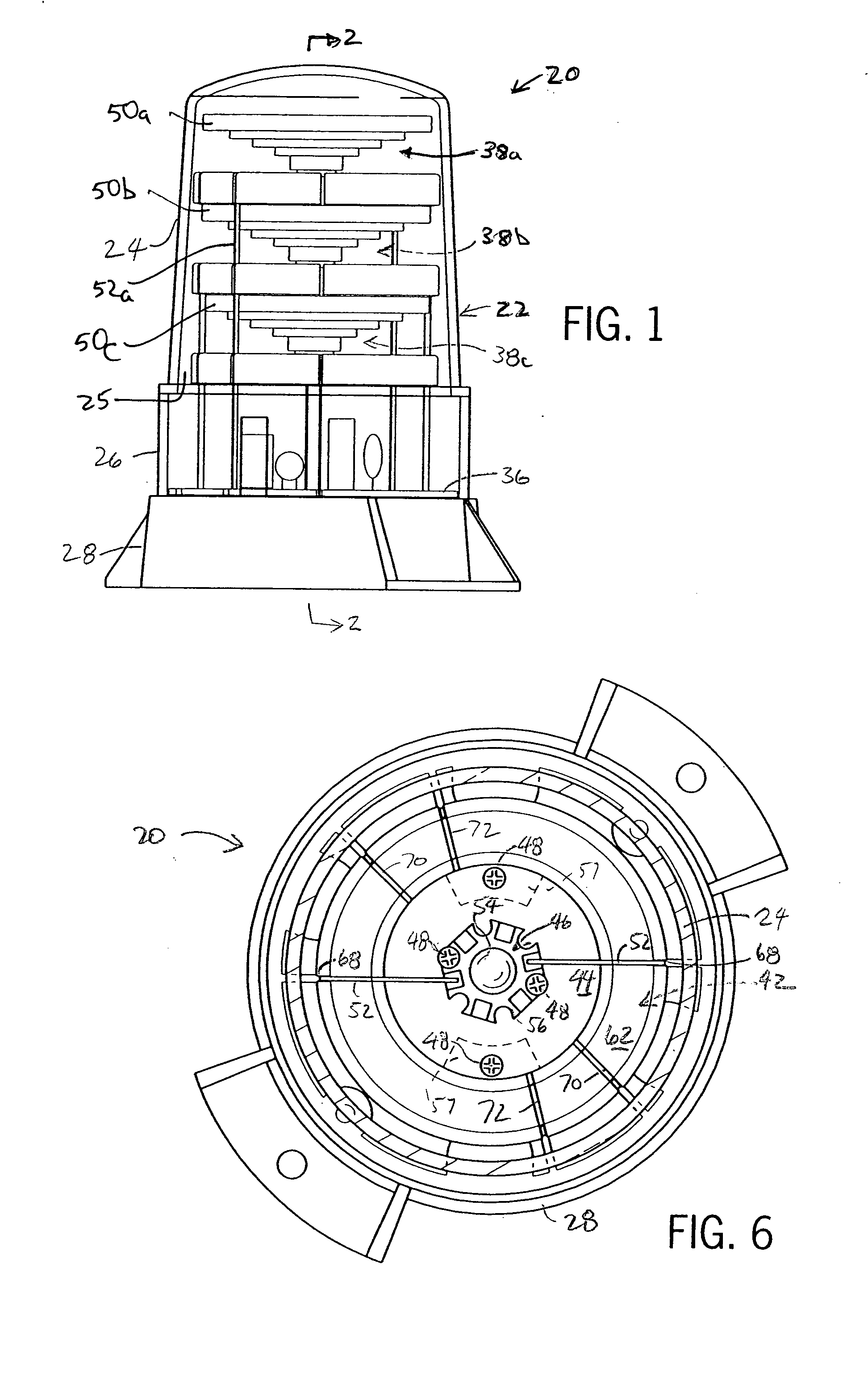
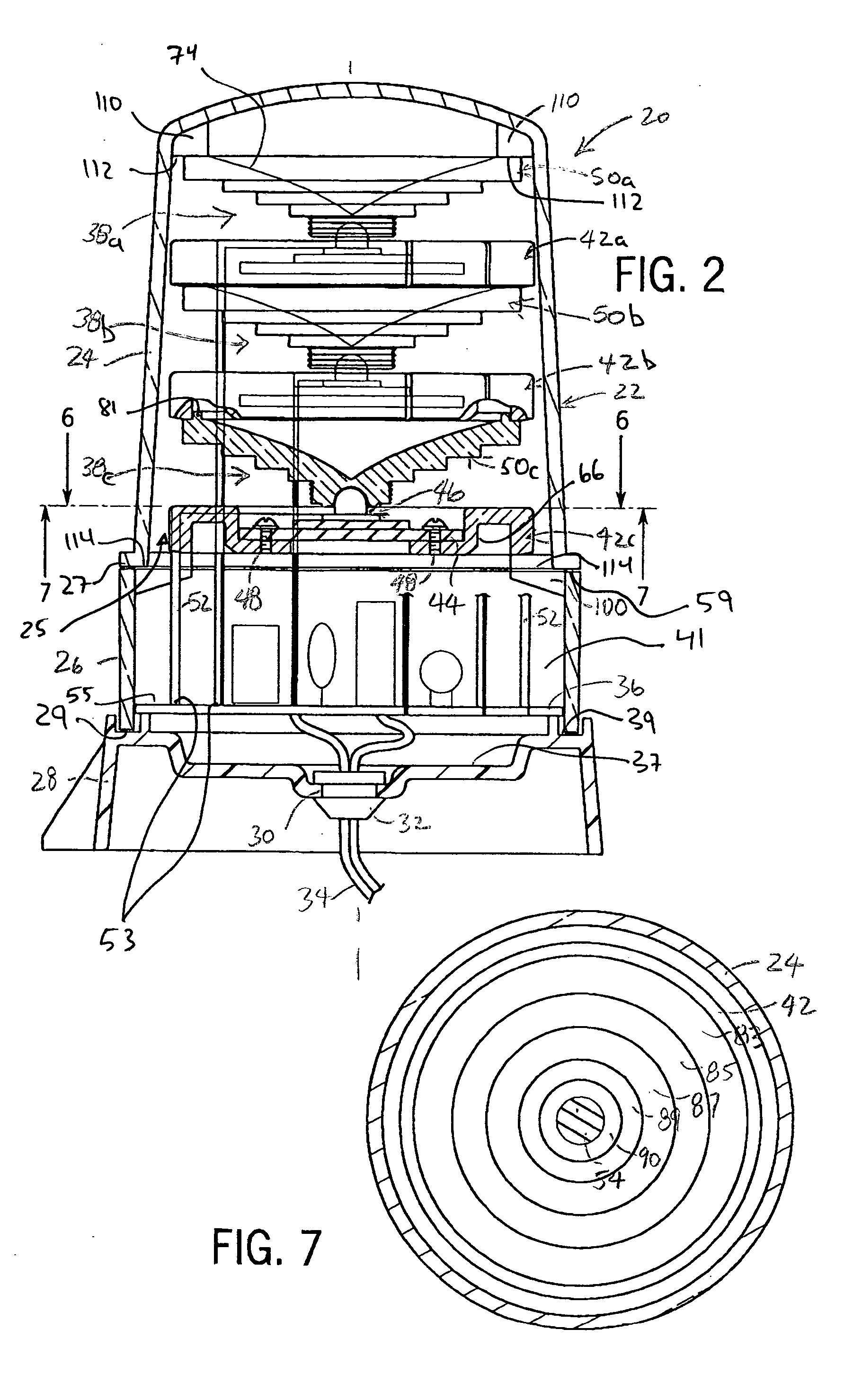
[0047] In the description that follows, while the light configurations described may be positioned in virtually any orientation (e.g., upright, on an angle, upside-down, etc.), in the interest of simplifying this explanation, relative directions and juxtapositions (e.g., top, bottom, left, right, above, etc.) will be indicated assuming the orientation illustrated in FIGS. 1 and 2.

[0048] The present invention will now be described in detail with reference to the figures, which show preferred light configurations. Referring to FIGS. 1-3, a first exemplary light assembly 20 includes a mounting member 28, an electronics housing member 26, a cover member 24, electronic driving circuitry 36 and three separate optical modules including an upper module 38a, a middle module 38b and a lower module 38c. Referring to FIGS. 1 and 2, mounting member 28 is generally a cylindrical rigid plastic member which forms an upwardly facing surface 37 and some type of mechanical structure for mounting asse...


PUM


Abstract

An at least partially translucent optical element for distributing light from a light source, the element comprising a hub member formed about a central axis, having an external surface between first and second ends and forming a recess within the first end that extends along the central axis substantially along a length of the hub member between the first and second ends for receiving the source, the external surface forming a lens for dispersing light directed thereat from within the recess out of the element and a reflecting member integral with and extending from the second end, the reflecting member including at least one external reflecting surface that reflects substantially all of the light directed into the reflecting member from within the recess back into the element.

Description

CROSS-REFERENCE TO RELATED APPLICATION [0001] Not applicable. STATEMENT OF FEDERALLY SPONSORED RESEARCH OR DEVELOPMENT [0002] Not applicable. BACKGROUND OF THE INVENTION [0003] 1. Technical Field [0004] The present invention relates to lighting devices and, more specifically, to lighting devices having light emitting diodes coupled with optical elements for radially projecting light. [0005] 2. Description of the Related Art [0006] Strobe lights, warning beacons and other lighting devices for commercial, industrial, military, law enforcement or other such applications typically include a light bulb (e.g., incandescent or xenon bulb) disposed inside of a translucent housing and associated electronics that drive the bulb in steady or pulsed operation. Often one or more reflectors are placed in the housing to focus or disperse the light emitted from the light bulb in a radially directed pattern. Hereinafter, unless indicated otherwise, strobe configurations that include bulbs will be re...

Claims


Application Information

Patent Timeline
Patent Type & Authority Applications(United States)
IPC IPC(8): B60Q1/26F21S8/00F21V5/04F21V7/00F21V9/08F21V29/00
CPCB60Q1/2611F21S10/06F21V5/045F21V7/0091F21Y2101/02F21V29/004F21W2111/00F21W2111/02F21V9/08F21Y2113/00F21V29/70F21Y2115/10
Inventor POPOVIC, DRAGOSLAV
Owner J W SPEAKER CORP
Why Eureka
Try Eureka