Method and apparatus for tracking error detection in optical disk driver

a technology of optical disk driver and error detection, applied in the direction of data recording, instruments, disposition/mounting of heads, etc., can solve the problems of tracking error signal generation, difficult to precisely control tracking in a high-density track structure, and decrease in the magnitude and gain of tracking error signal according to the conventional dpd te method, etc., to achieve the effect of improving such drawbacks

Inactive Publication Date: 2005-03-31
SAMSUNG ELECTRONICS CO LTD
View PDF14 Cites 9 Cited by
  • Summary
  • Abstract
  • Description
  • Claims
  • Application Information

AI Technical Summary

Benefits of technology

[0011] In order to improve such drawbacks, a tracking error detecting method according to the present invention involves generating clock signals, synchronized with each of the binarized signals AC3 and BD3, to detect a phase difference betw...

Problems solved by technology

In addition, as the track density of an optical disk increases, the magnitude and gain of a tracking error signal according to the conventional DPD TE method decrease.
Thus, the conventional DPD TE method has a disadvantage in that it is difficult to precisely control tracking in a high-density track structure.
Thus, a tracking error signal is generated by detecting the time delay between ...

Method used


Image

  • Method and apparatus for tracking error detection in optical disk driver
  • Method and apparatus for tracking error detection in optical disk driver
  • Method and apparatus for tracking error detection in optical disk driver

Examples


Embodiment Construction

[0030] Reference will now be made in detail to the present preferred embodiments of the present invention, examples of which are illustrated in the accompanying drawings, where like reference numerals refer to like elements throughout.

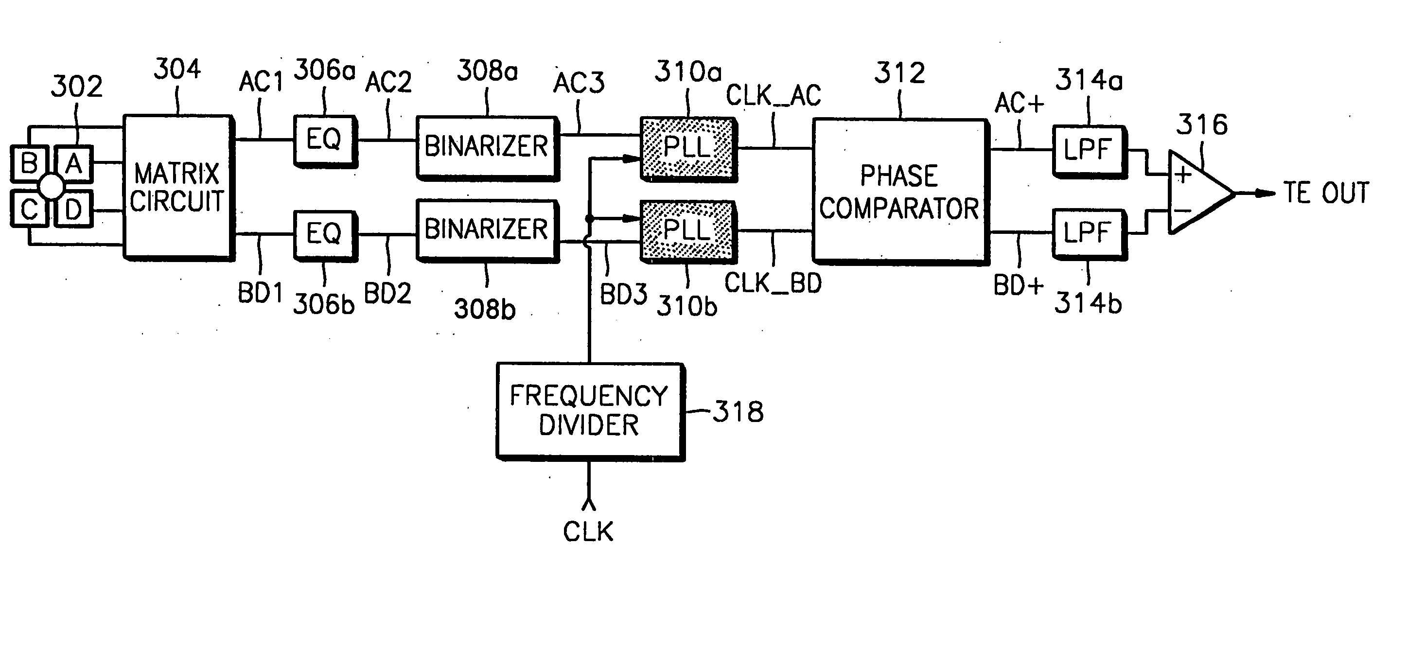
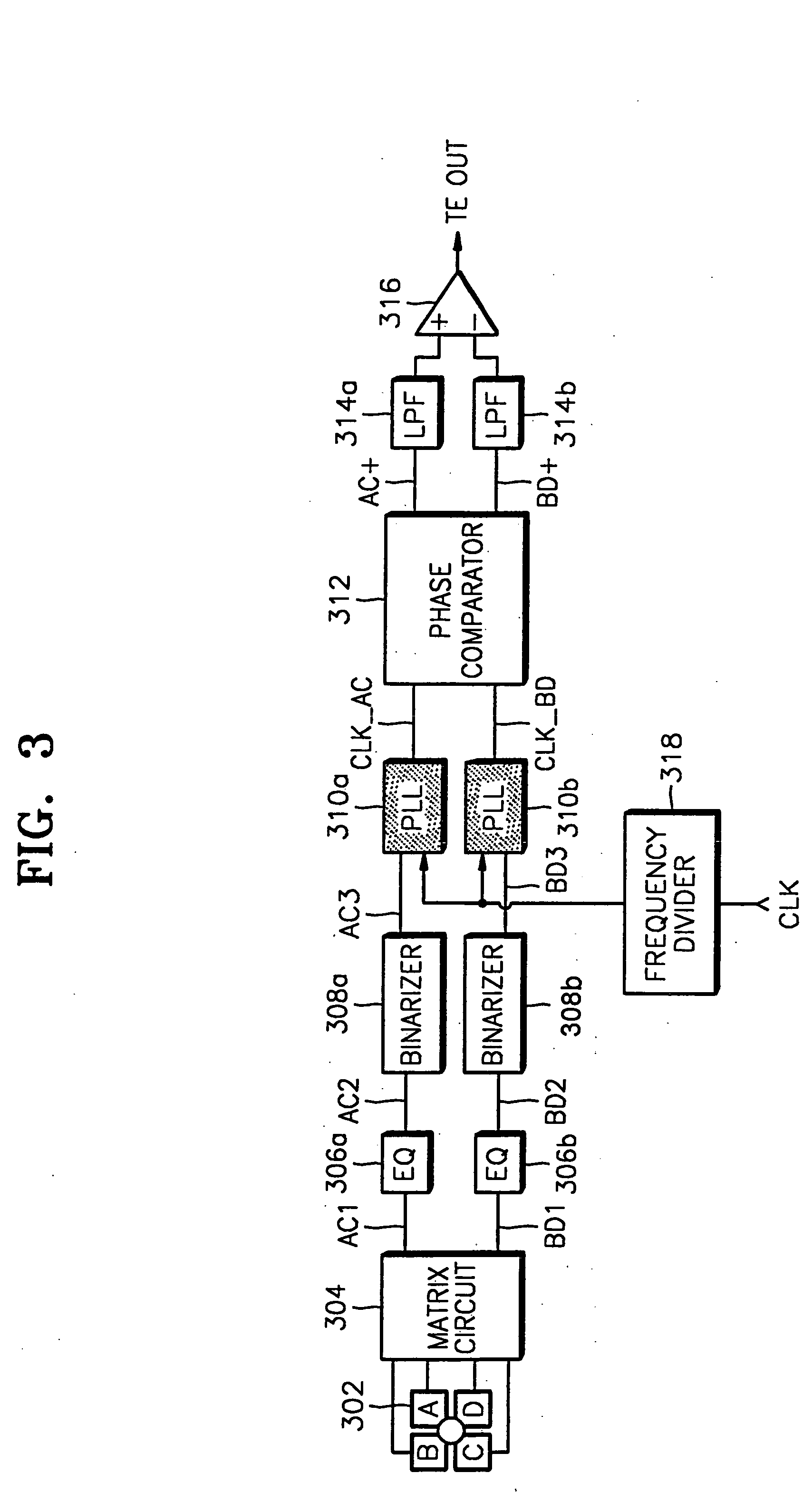
[0031]FIG. 3 is a block diagram showing a first preferred embodiment of a tracking error detecting apparatus according to the present invention. The apparatus shown in FIG. 3 includes a four-section optical detection unit 302, a matrix circuit 304, equalizers (EQs) 306a and 306b, binarizers 308a and 308b, PLLs 310a and 310b, a phase comparator 312, LPFs 314a and 314b, a differential amplifier 316, and a frequency divider 318.

[0032] The matrix circuit 304 adds optical detection signals A and C, and B and D among the outputs A, B, C and D of the four-section optical detection unit 302, and outputs AC1 and BD1 corresponding to A+C and B+D, respectively. That is, the matrix circuit 304 produces summation signals of the signals generated by optical detect...


PUM


Abstract

A method and apparatus for tracking error detection in an optical disk reproduction system. The tracking error detecting apparatus generates a tracking error signal as a difference signal of optical detection signals generated by more than two optical detectors positioned along a diagonal line from a track center and includes binarizers which binarize each output of the optical detectors, phase locked loops (PLLs) which generate respective clock signals synchronized with the outputs of each of the binarizers, a phase difference detector which detects a phase difference between the synchronized signals output from the PLLs, and low-pass filters which filter the output of the phase difference detector to output the result as the tracking error signal. The tracking error detecting apparatus generates a tracking error signal which is not dependent on the lengths of pits or marks recorded on an optical disk, enhancing the reliability of the tracking error signal.

Description

CROSS-REFERENCE TO RELATED APPLICATIONS [0001] This application is a divisional of prior application Ser. No. 09 / 613,695, filed Jul. 10, 2000, which is incorporated herein in its entirety by reference. This application claims the benefit of Korean Application No. 99-27451, filed Jul. 8, 1999, in the Korean Patent Office, the disclosure of which is incorporated herein by reference.BACKGROUND OF THE INVENTION [0002] 1. Field of the Invention [0003] The present invention relates to a method and apparatus for tracking error detection and more particularly, to an improved method and apparatus for tracking error detection in which a phase locked loop (PLL) is introduced into a conventional differential phase detection tracking error (DPD TE) method to increase the accuracy of tracking error detection. [0004] 2. Description of the Related Art [0005] In a conventional DPD TE method, phase differences are generated on the edges of pits or marks of an optical disk. The length of pits or marks...

Claims


Application Information

Patent Timeline
IPC IPC(8): G11B7/09
CPCG11B7/0901
Inventor MA, BYUNG-INPARK, IN-SIKSEO, JOONG-EONSHIM, JAE-SEONG
Owner SAMSUNG ELECTRONICS CO LTD
Why Eureka
Try Eureka