Centralized radio network controller

a radio network controller and central control technology, applied in the field of wireless communication systems, can solve the problems of increasing the cost of providing a distributed rnc architecture, not always synchronizing, and expensive hardware elements of rncs, so as to improve the integration with internet protocol (ip) networks, improve the efficiency of processing transmission data, and improve the effect of radio resource managemen

Inactive Publication Date: 2005-03-31
INTERDIGITAL TECH CORP
View PDF8 Cites 66 Cited by
  • Summary
  • Abstract
  • Description
  • Claims
  • Application Information

AI Technical Summary

Benefits of technology

[0015] In a wireless communication network, the system and method of the present invention separate U-Plane data from C-Plane data at a Node B or at a base station to more efficiently process transmission data, improve Radio Resource Management (RRM), and provide improved integration with Internet Protocol (IP) networks. The user da

Problems solved by technology

Since the CN 100 is limited in terms of how fast it can reroute the U-Plane and the C-Plane from one RNC to another, it is not always possible to synchronize the relocation of the U-Plane and the C-Plane functions from the CN 100 to the new C-RNC 107.
RNCs are expensive hardware elements since they must support both U-Plane and C-Plane functions.
The cost of providing a distributed RNC architecture escalates in regions where RNCs are called upon to handle relatively large amounts of U-Plane traffic.
Additionally, in rural areas where U-Plane data communication requirements are distributed over large areas, it may not be economically feasible to provision terrestrial resources in the form of a centralized point of presence.
Another drawback with an arc

Method used


Image

  • Centralized radio network controller
  • Centralized radio network controller
  • Centralized radio network controller

Examples


Embodiment Construction

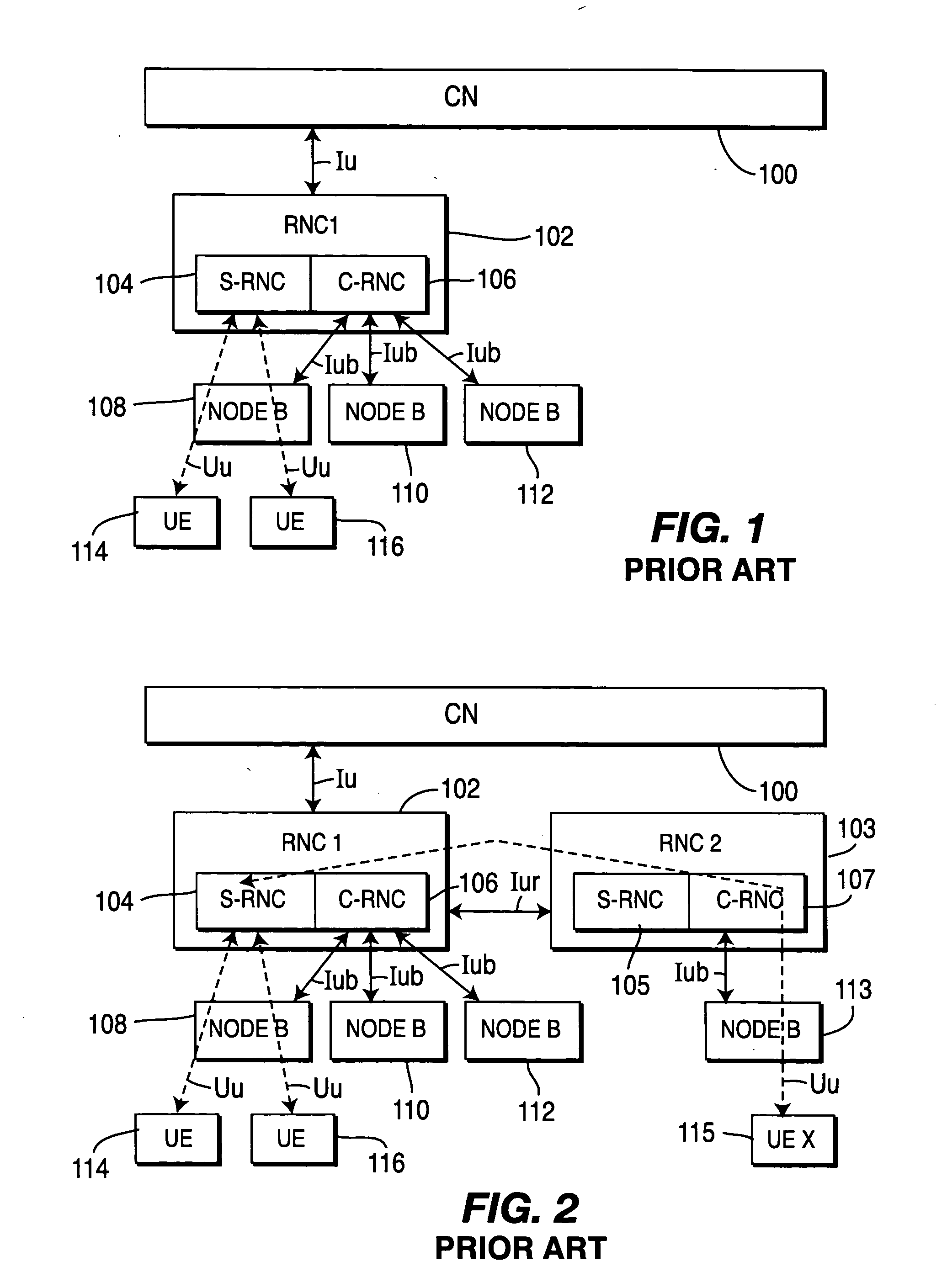
[0023] Hereinafter, the terminology “wireless transmit / receive unit” (WTRU) includes but is not limited to a user equipment, mobile station, fixed or mobile subscriber unit, pager or any other type of device capable of operating in a wireless environment. In CDMA systems specified by the Third Generation Partnership Project (3GPP), base stations are called Node Bs and subscriber units are called User Equipment (UEs). When referred to hereinafter, the terminology “base station” includes but is not limited to a Node-B, site controller, access point or other interfacing device in a wireless environment.

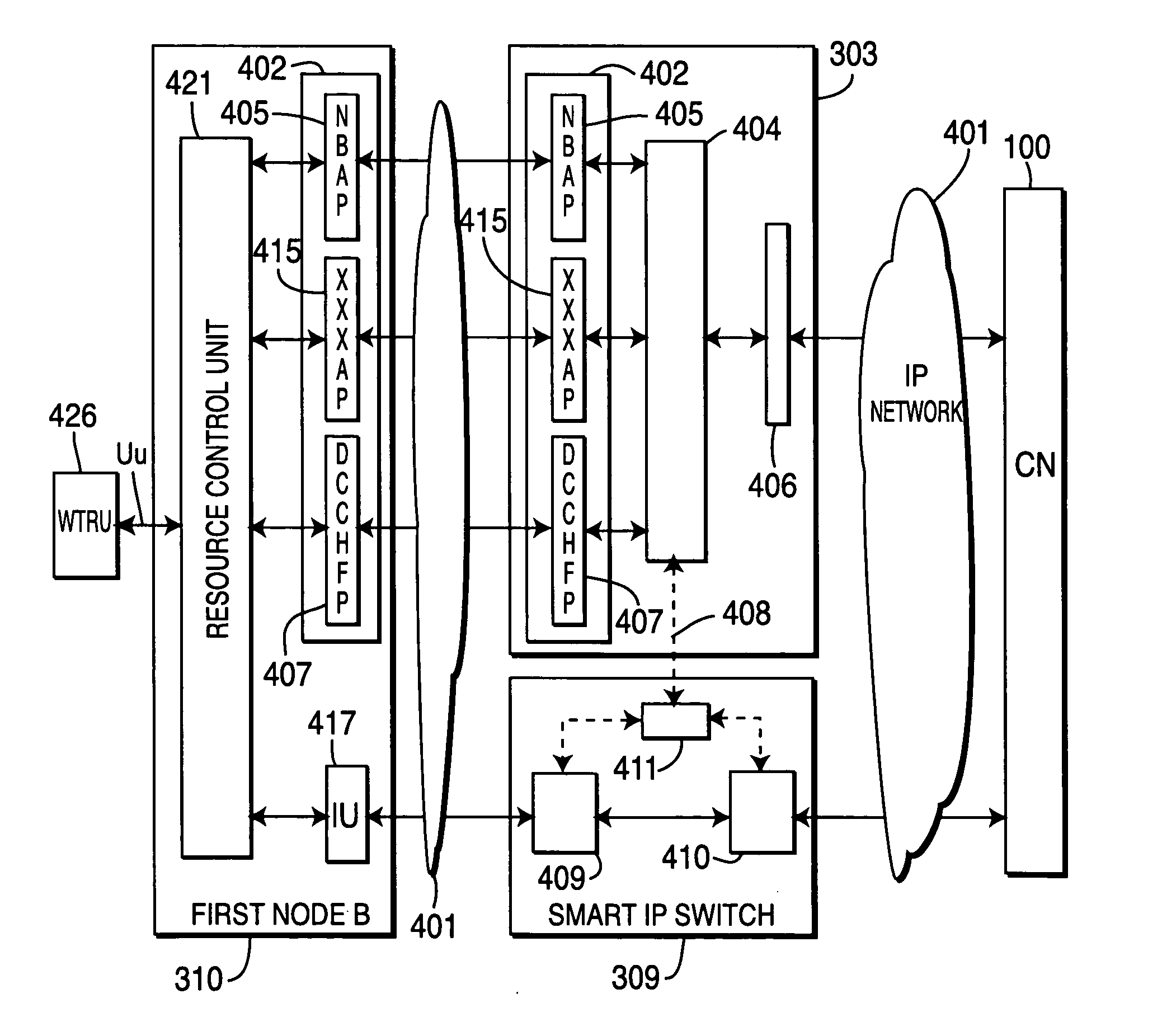
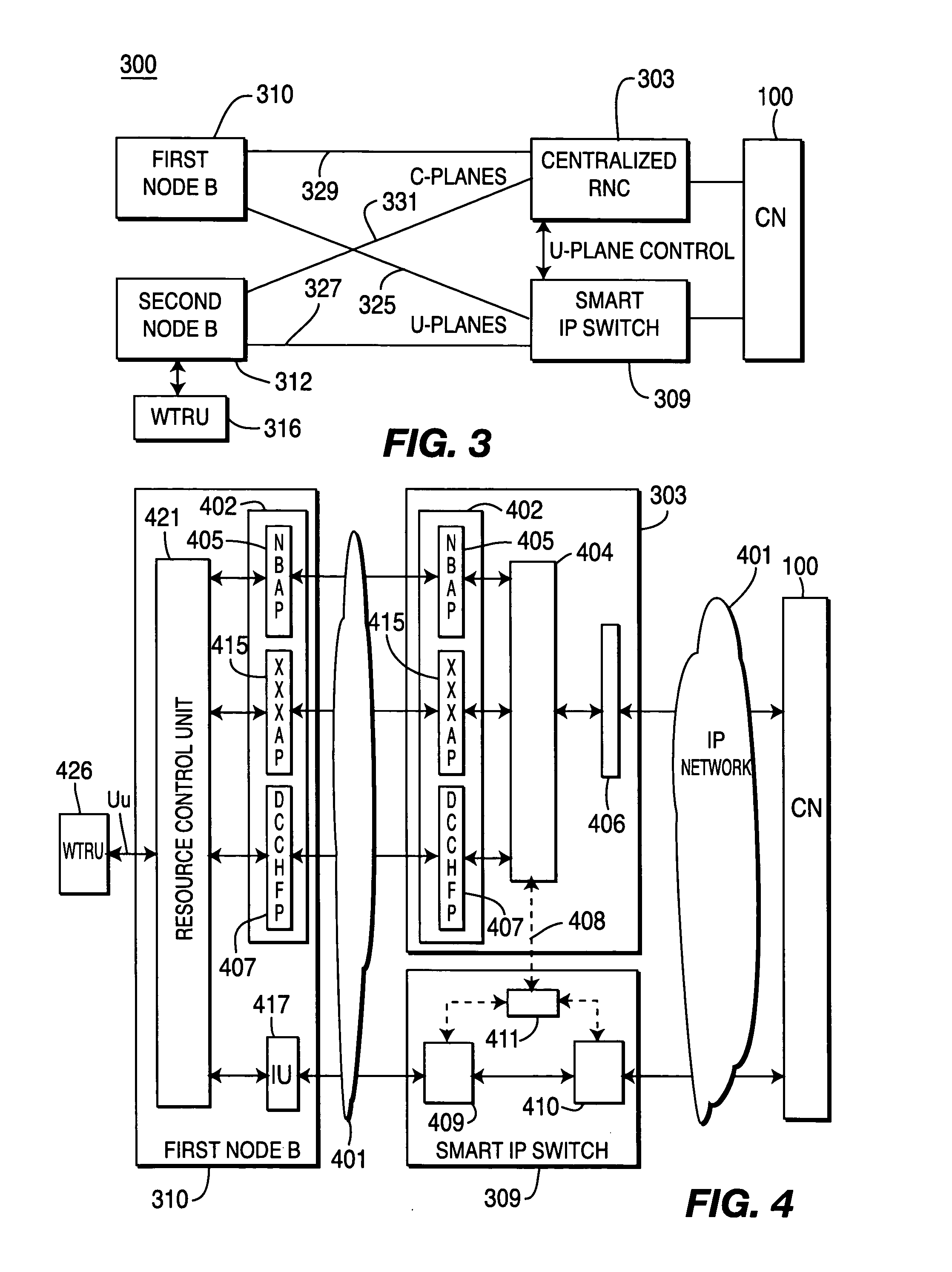
[0024] In accordance with the present invention, transmission data is more efficiently processed, RRM performance is improved, and integration with IP networks is improved by separating user data from connection management and control data, (hereinafter, “control data”). The user data is routed to a smart IP switch, whereas the connection management and control data is routed to a centr...


PUM


Abstract

In a radio access network, novel systems and methods reduce processing delay, and improve integration with IP networks, by separating user data from connection management and control data at a Node B or at a base station. The user data are routed to an IP (Internet Protocol) switch, whereas the connection management and control data are routed to a centralized radio network controller (RNC). Pursuant to a second embodiment of the invention, a centralized RNC provides improved radio resource management (RRM) functionality by handing all connection management and control data for a plurality of Node B's, thereby simplifying the switching of user data throughout the radio access network. Pursuant to a third embodiment of the invention, a smart IP switch is equipped to switch user data without core network (CN) involvement. Downlink user data are switched independently of uplink user data.

Description

CROSS REFERENCE TO RELATED APPLICATION [0001] This application claims priority from U.S. patent application Ser. No. 60 / 507,805, filed Sep. 30, 2003 which is incorporated by reference as if fully set forth.FIELD OF THE INVENTION [0002] The present invention relates generally to wireless communication systems. More specifically, the present invention is directed to an improved radio network controller (RNC) and Universal Terrestrial Radio Access Network (UTRAN) architecture for more efficiently processing of user data and control signaling. BACKGROUND [0003] Current wireless communication networks typically utilize a distributed radio access architecture. For example, the Third Generation Partnership Project (3GPP) universal terrestrial radio access network (UTRAN), utilizes a distributed RNC architectural configuration as shown in FIG. 1. A serving RNC (S-RNC) 104 manages one or more user equipment (UEs) 114, 116. User and control data from an S-RNC 104 is passed directly through a ...

Claims


Application Information

Patent Timeline
IPC IPC(8): H04W80/04H04W88/12H04W92/04H04W92/12
CPCH04L47/14H04W80/04H04W40/36H04W92/045H04W92/12H04W88/12H04W8/04
Inventor TERRY, STEPHEN E.MILLER, JAMES M.
Owner INTERDIGITAL TECH CORP
Why Eureka
Try Eureka