Method and apparatus for controlling the flow resistance of a fluid on nanostructured or microstructured surfaces

a nanostructured or microstructured surface, flow resistance technology, applied in the direction of fluid speed measurement, air flow influencers, underwater vessels, etc., can solve the problem of droplet movement, difficult or impossible control of liquid movement, and liquid flow resistance to such a level, so as to reduce the flow resistance of fluid

Active Publication Date: 2005-03-31
ALCATEL LUCENT SAS
View PDF8 Cites 42 Cited by
  • Summary
  • Abstract
  • Description
  • Claims
  • Application Information

AI Technical Summary

Benefits of technology

[0007] While prior attempts to reduce the flow resistance of a fluid in contact with a surface are advantageous in many regards, we have realized that it would be extremely advantageous to be able to control the degree of penetration of a fluid disposed on a nanostructured or microstructured surface. Therefore, we have invented a method and apparatus wherein, in a first illustrative embodiment, a closed-cell nanstructured or microstructured surface is used in a way such that, when the pressure of at least a first fluid within one or more of the cells of said surface is decreased to or below a desired level, a droplet disposed on that surface is caused to at least partially penetrate the surface. In another illustrative embodiment, the pressure within one or more of the cells is increased to or above a desired level in a way such that the droplet of liquid is returned at least partially to its original, unpenetrated position. In this way, the penetration of the droplet into the surface can be varied to achieve a desired level of flow resistance experienced by the droplet of liquid.
[0008] In yet another embodiment, a closed-cell structure feature pattern is used to prevent penetration of the nanostructured or microstructured surface, even when the pressure of the fluid disposed on the surface is relatively high.

Problems solved by technology

However, as exemplarily taught by the Kim reference, the flow resistance to the liquid is reduced to such a level that it was difficult or impossible to control the movement of the liquid.
The resulting force imbalance causes the droplet to move in the direction of the leading edge.

Method used


Image

  • Method and apparatus for controlling the flow resistance of a fluid on nanostructured or microstructured surfaces
  • Method and apparatus for controlling the flow resistance of a fluid on nanostructured or microstructured surfaces
  • Method and apparatus for controlling the flow resistance of a fluid on nanostructured or microstructured surfaces

Examples


Embodiment Construction

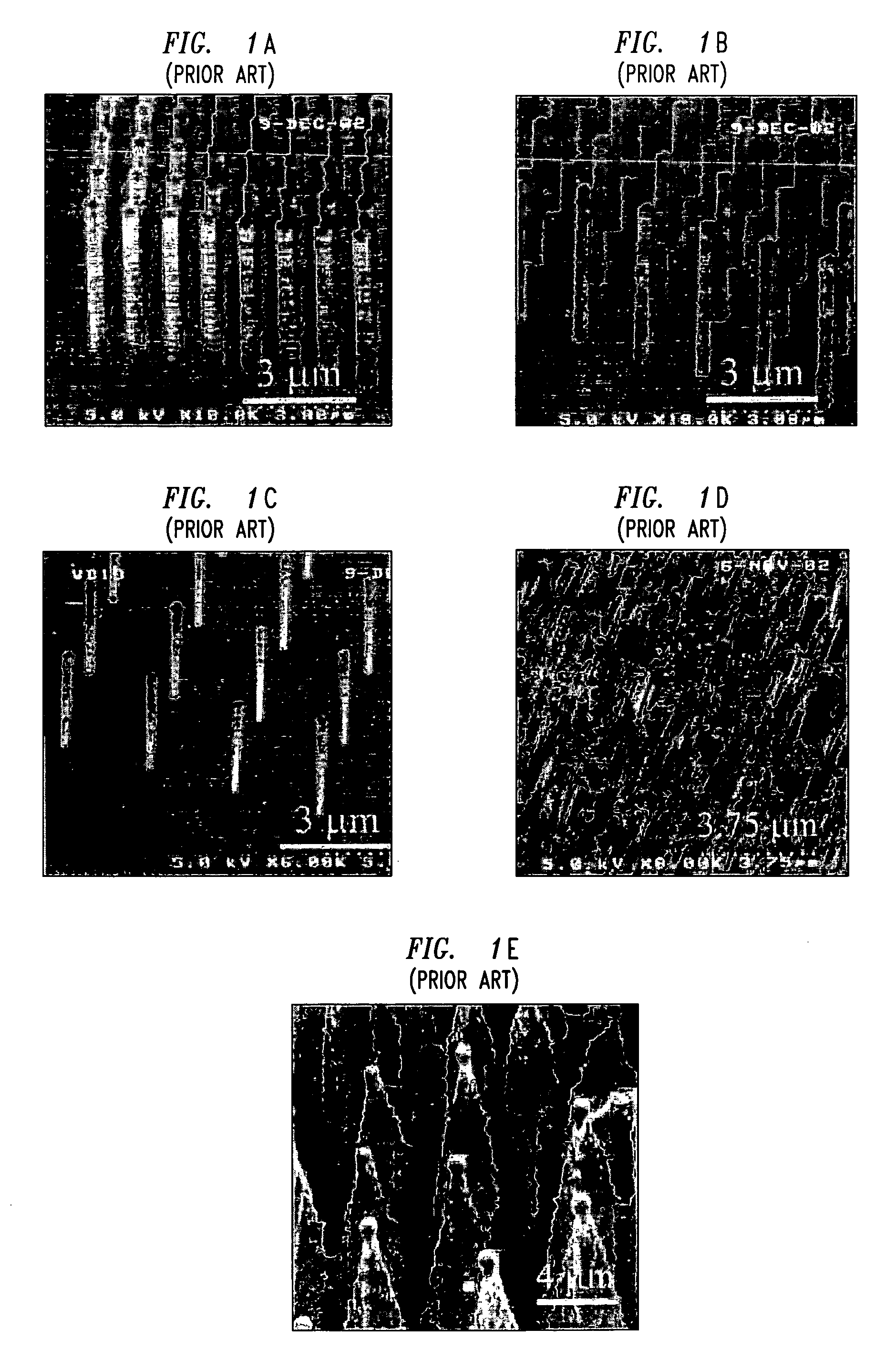
[0024] As described above, microstructures and nanostructures have been used recently to reduce the flow resistance of experienced by a liquid as it moves across a surface. Such prior micro- or nanostructures can take many forms. For example, FIGS. 1A-1E show different illustrative prior art arrangements of nanoposts produced using various methods and further show that such various diameter nanoposts can be fashioned with different degrees of regularity. These figures show that it is possible to produce nanoposts having various diameters separated by various distances. An illustrative method of producing nanoposts, found in U.S. Pat. No. 6,185,961, titled “Nanopost arrays and process for making same,” issued Feb. 13, 2001 to Tonucci, et al, is hereby incorporated by reference herein in its entirety. Nanoposts have been manufactured by various methods, such as by using a template to form the posts, by various means of lithography, and by various methods of etching. As used herein, un...


PUM


Abstract

A method and apparatus is disclosed wherein the flow resistance of a droplet disposed on a nanostructured or microstructured surface is controlled. A closed-cell feature is used in a way such that, when the pressure of at least a first fluid within one or more of the cells of said surface is decreased to or below a desired level, a droplet disposed on that surface is caused to at least partially penetrate the surface. In another illustrative embodiment, the pressure within one or more of the cells is increased to or above a desired level in a way such that the droplet of liquid is returned at least partially to its original, unpenetrated position. In yet another embodiment, a closed-cell structure feature pattern is used to prevent penetration of the nanostructured or microstructured surface, even when the pressure of the fluid disposed on the surface is relatively high.

Description

FIELD OF THE INVENTION [0001] The present invention relates generally to the motion of liquids disposed on a surface with extremely small, predetermined surface features and, more particularly, to controlling flow resistance experienced by a liquid disposed on a surface with predetermined nanostructure or microstructure features BACKGROUND OF THE INVENTION [0002] Many beneficial devices or structures in myriad applications are characterized at least in part by having a liquid that is in contact with at least one solid surface. Recent applications have focused on the movement of small droplets of liquid disposed on nanostructured or microstructured surfaces which can be manufactured by various methods, such as various means of lithography or etching. Such surfaces result in surfaces that are useful for significantly reducing flow resistance experienced by droplets of liquid disposed on the surfaces. [0003] One such application is described in “Nanostructured Surfaces for Dramatic Red...

Claims


Application Information

Patent Timeline
Patent Type & Authority Applications(United States)
IPC IPC(8): B01L3/00B82B1/00B81B1/00B81B7/04B82B3/00F15C1/00F15C1/04
CPCB01L3/5088B01L2300/16Y10T436/2575B82Y20/00B01L2400/0442Y10T137/0396F15C1/04B82B3/00B82Y40/00B81B7/04
Inventor HODES, MARC SCOTTKOLODNER, PAUL ROBERTKROUPENKINE, TIMOFEI NIKITALYONS, ALAN MICHAELMANDICH, MARY LOUISETAYLOR, JOSEPH ASHLEY
Owner ALCATEL LUCENT SAS
Why Eureka
Try Eureka