Method and device for generating sheet metal model from solid model

a solid model and sheet metal technology, applied in the direction of total factory control, programme control, instruments, etc., can solve the problems of difficult to represent the shape of a sheet metal product having a thickness, long time for modeling a product, and burdensome operation

Active Publication Date: 2005-03-31
FUJITSU LTD
View PDF5 Cites 11 Cited by
  • Summary
  • Abstract
  • Description
  • Claims
  • Application Information

AI Technical Summary

Benefits of technology

[0009] An object of the present invention is to provide a method and a device for generating a sheet metal model that can be unfolded automatically, from a solid model obtained by modeling a schematic solid shape of a sheet metal product by an easy operation in a three-dimensional sheet metal CAD / CAM system.
[0016] According to the method and the device of the present invention, a user can generate a sheet metal model in a simple operation that can be unfolded automatically, from a solid model obtained by modeling an outer shape of a sheet metal product. As a result, man-hours necessary for generating a development in a design division and a process division can be reduced substantially.
[0017] According to the preferred embodiment, the user can save operation strokes and time for entering an attribution that is used for generating a sheet metal model. In addition, an input error, i.e., designation of a thickness and a material of a sheet metal that are not registered as a possible combination can be avoided.

Problems solved by technology

In the above-mentioned first conventional method for generating a sheet metal model, there is a case where it is difficult to represent a shape of a sheet metal product having a thickness.
Such an operation is burdensome with some difficulty when the shape becomes complicated.
In addition, the above-mentioned second conventional method for generating a sheet metal model has a disadvantage that it takes a long time for modeling a product.

Method used


Image

  • Method and device for generating sheet metal model from solid model
  • Method and device for generating sheet metal model from solid model
  • Method and device for generating sheet metal model from solid model

Examples


Embodiment Construction

[0030] Hereinafter, the present invention will be explained more in detail with reference to embodiments and drawings.

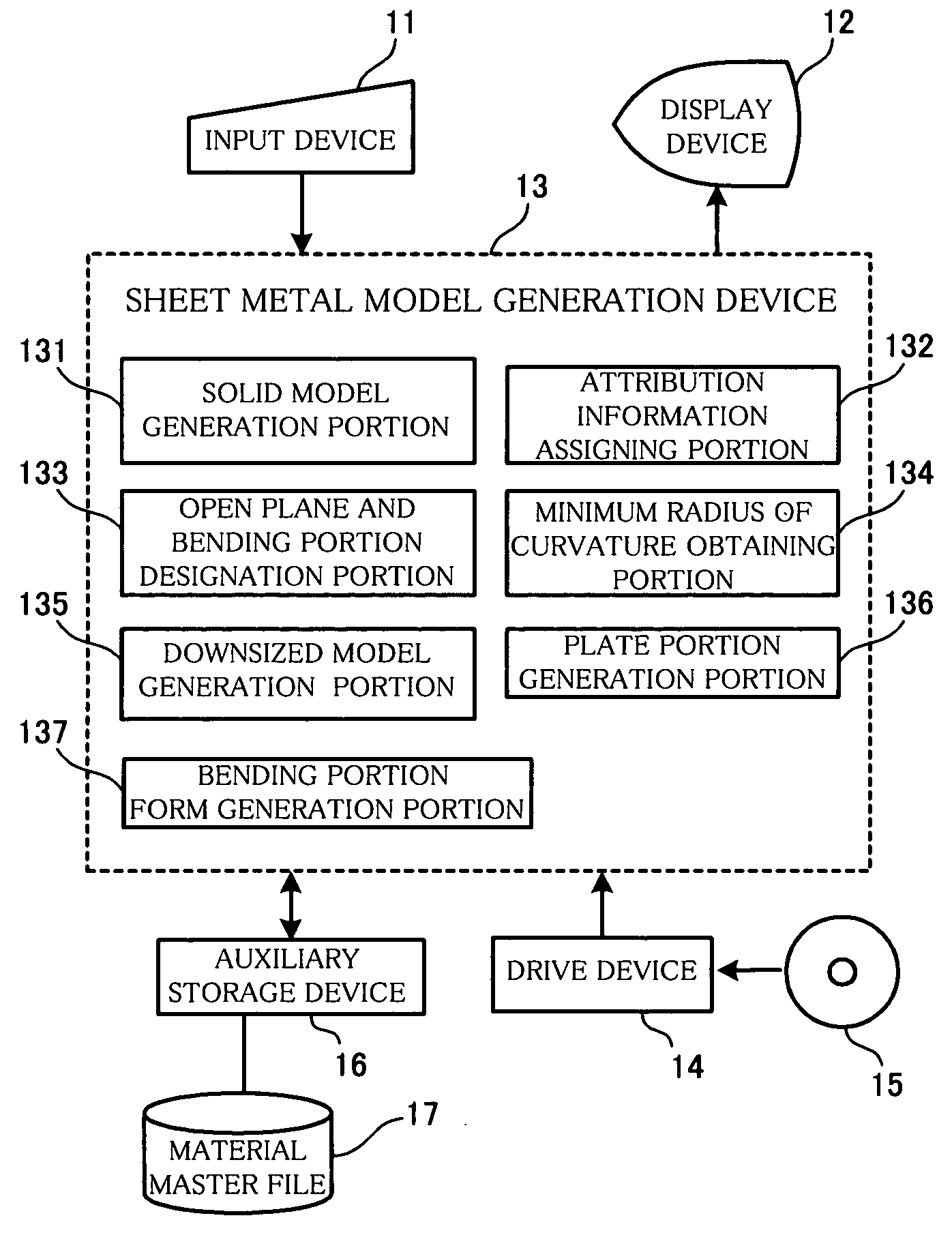
[0031]FIG. 5 is a block diagram showing a structure including a sheet metal model generation device in a CAD / CAM system according to an example of the present invention. A computer system that is used for a CAD process in a CAD / CAM system is shown. This system is constituted by installing a CAD program (software) into a computer system such as a personal computer. The computer system includes a central processing unit (CPU), a main memory, an input device 11 such as a keyboard or a mouse, a display device 12 such as a CRT or an LCD, an auxiliary storage device 16 such as a hard disk drive, and a drive device 14 for a removable storage medium.

[0032] A CAD program that constitutes the sheet metal model generation device according to the present invention is supplied in a form recorded on a removable storage medium 15 such as an optical disk (CD-ROM) and is installed ...


PUM


Abstract

The method includes the steps of assigning entered attribution information including material and thickness of a sheet metal to a specified solid model, assigning entered designation information for designating an open plane and a bending portion to the solid model, obtaining a minimum radius of curvature at the bending portion from the material and the thickness of the sheet metal, generating a downsized model defined by the designated open plane and a plurality of planes that are generated by moving a plurality of planes of the solid model except the open plane inward in parallel by a distance that is a sum of the thickness of the sheet metal and the minimum radius of curvature, generating inner wall surfaces by moving a plurality of surfaces of the downsized model except for the open plane outward in parallel by a distance that is equal to the minimum radius of curvature, generating plate portions by a projection process in which the inner wall surfaces are further moved outward in parallel by a distance that is equal to the thickness of the sheet metal, and generating a bending portion form that is a fillet connecting neighboring plate portions at the bending portion designated in the solid model.

Description

BACKGROUND OF THE INVENTION [0001] 1. Field of the Invention [0002] The present invention relates to a method and a device for generating a sheet metal model that can be unfolded automatically, from a solid model obtained by modeling a schematic solid shape of a sheet metal product, by a simple operation in a three-dimensional sheet metal CAD / CAM system. [0003] 2. Description of the Prior Art [0004] In the conventional three-dimensional sheet metal CAD / CAM system, a sheet metal model is usually generated by one of the two methods explained as below. A first method is shown in FIG. 1. In this method, a so-called paper model having zero thickness as shown in (a) is generated first. Then, a sheet metal model as shown in (b) is generated by offsetting the paper model in the thickness direction. This type of method for generating a sheet metal model is explained in Japanese unexamined patent publication No. 11-175575, for example. [0005] A second conventional method for generating a shee...

Claims


Application Information

Patent Timeline
Patent Type & Authority Applications(United States)
IPC IPC(8): G05B19/4097G06F17/50
CPCG05B19/4097G05B2219/35018G05B2219/45143G05B2219/36284G05B2219/35113Y02P90/02
Inventor ITOH, SHINYA
Owner FUJITSU LTD
Why Eureka
Try Eureka