
Closing wheel arm pivot assembly

a technology of pivot assembly and closing wheel arm, which is applied in the field of pivot assembly, can solve the problems of reducing the effectiveness of the pivot assembly, no practical way to repair the pivot assembly, and the bearing housing b>14/b> was especially expensive and time-consuming to replace, so as to improve the performance of the closing wheel arm pivot and facilitate installation. , the effect of increasing the longevity

Inactive Publication Date: 2005-04-07
KESTER PHILIP C
View PDF12 Cites 43 Cited by
  • Summary
  • Abstract
  • Description
  • Claims
  • Application Information

AI Technical Summary

Benefits of technology

[0017] Another object of the present invention is to provide an improved pivot assembly that can be used for increasing the longevity and improving the performance of closing wheel arm pivots, press wheel arm pivots, and other oscillating load applications.
[0018] Another object of the present invention is to provide a repair kit for an oscillating load pivot assembly that is easy to install, that is dependable and capable of a long service life, that is economical to manufacture, and that is particularly well suited for use in repairing closing wheel arm pivot assemblies for no-till drills.
[0021] According to another broad aspect of the present invention, a closing wheel arm assembly for attaching a closing wheel to an agricultural seeder is provided, comprising: a bearing housing mounted on the agricultural seeder, the bearing housing having a bore extending therethrough; a closing wheel arm having a first end pivotally mounted to the bearing housing and a second end on which a closing wheel is pivotally mounted; a pair of sleeve bearings press fit into opposite ends of the bore of the bearing housing, the sleeve bearings each having at least one groove formed across a bearing surface thereof for allowing grease to flow to outer ends of the bearings; a pair of seals press fit into the opposite ends of the bore of the bearing housing and arranged to keep dirt out of and grease in the pivot assembly; and a pivot bushing or pivot pin fixed at the first end of the pivot arm and extending through the sleeve bearings, an outer surface of the pivot bushing or pivot pin providing a close-running fit with the bearing surfaces of the sleeve bearings.

Problems solved by technology

All of these named components are supported by a single, large and complicated support casting.
The press wheel arm pivot is a similar design and has similar durability problems but to a lesser extent.
Another bad effect is that the looser the pivot is, the greater the tendency for the closing wheel 17 to bounce, which also reduces its effectiveness.
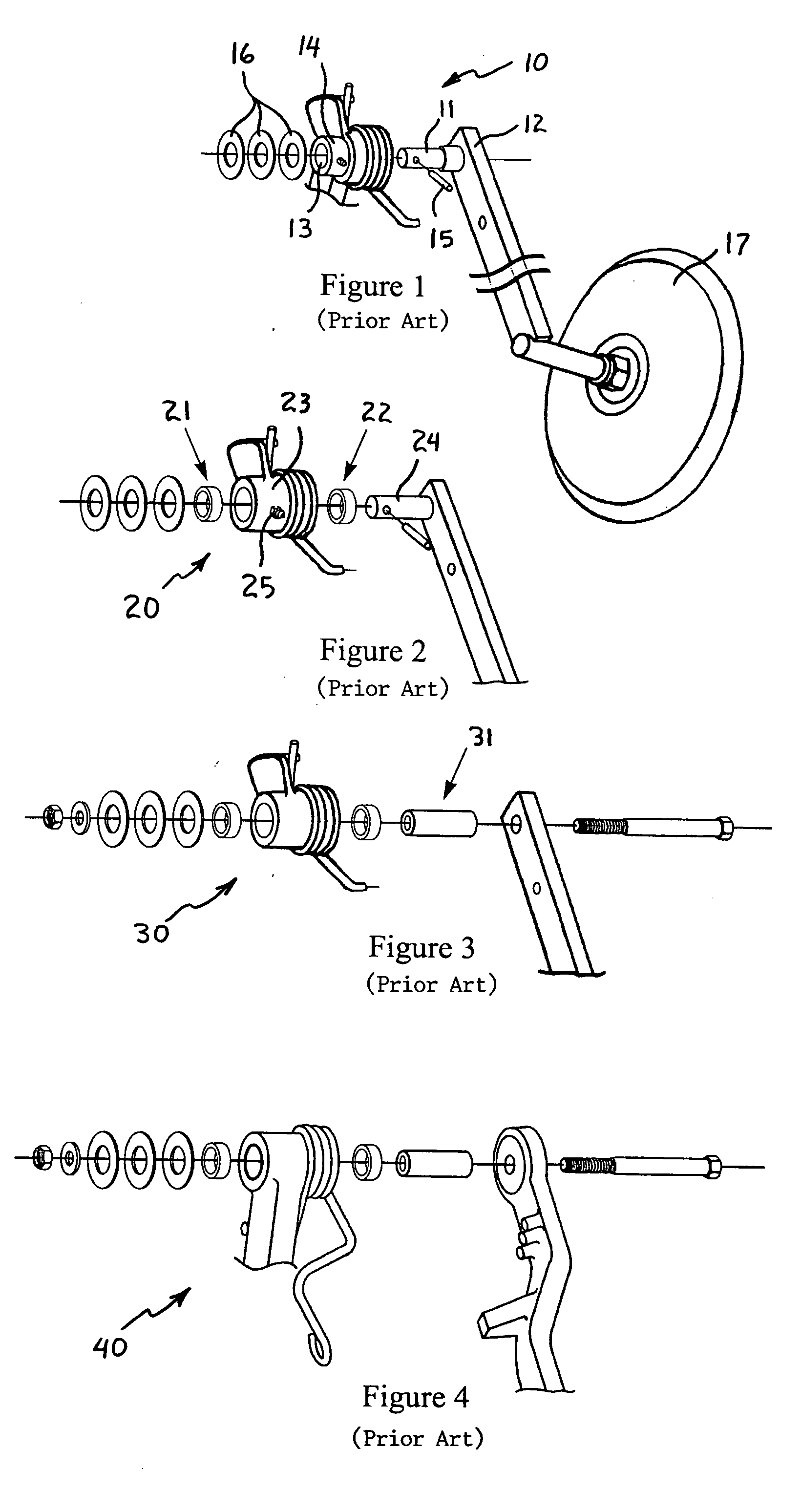
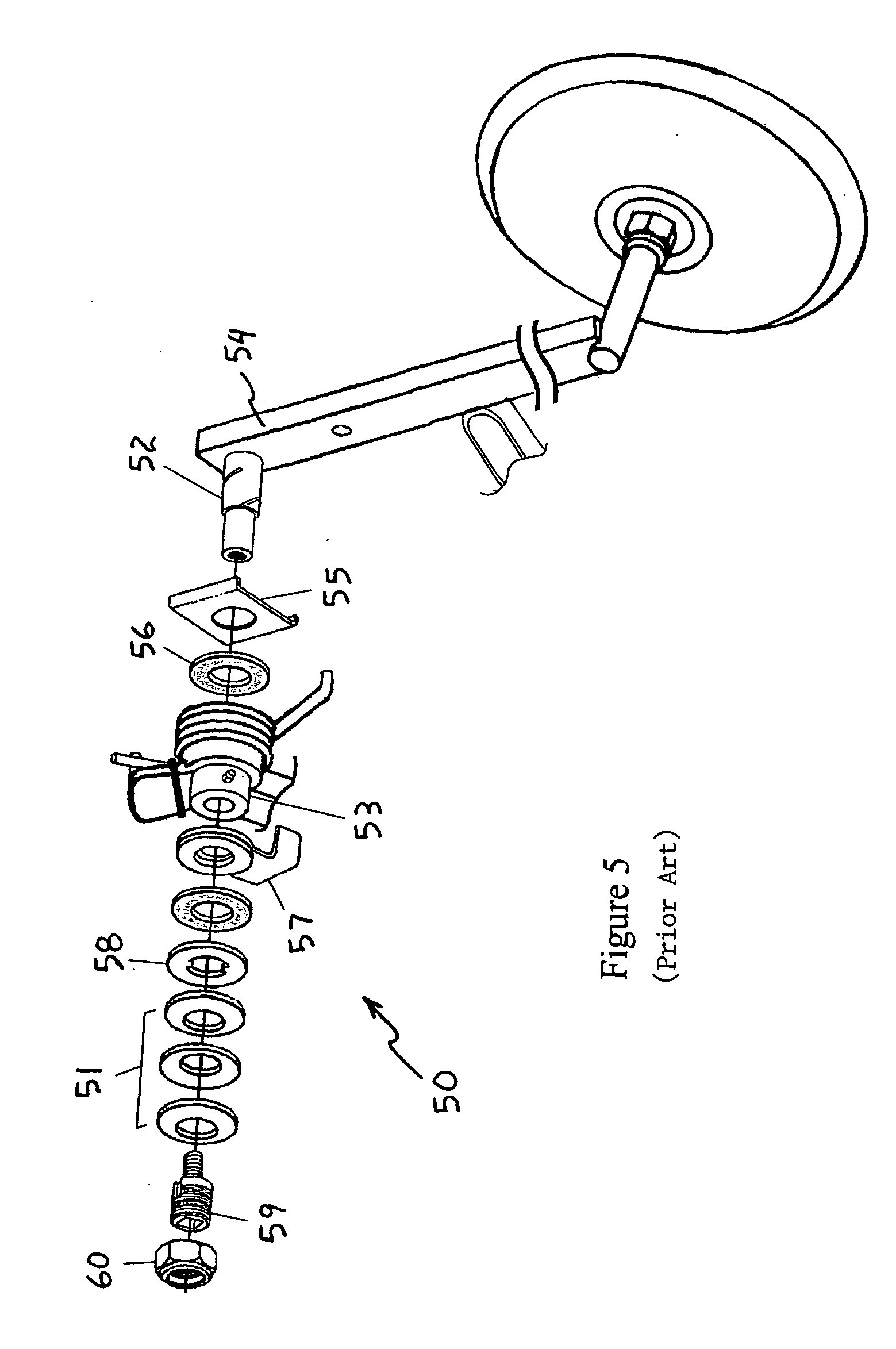
There was no practical way to repair this pivot arm assembly 10 in the original design.
The bearing housing 14 was especially expensive and time consuming to replace and clearly this was not practical.
It did not however improve the durability significantly.
However, durability was unaffected.

Method used


Image

  • Closing wheel arm pivot assembly
  • Closing wheel arm pivot assembly
  • Closing wheel arm pivot assembly

Examples


first embodiment

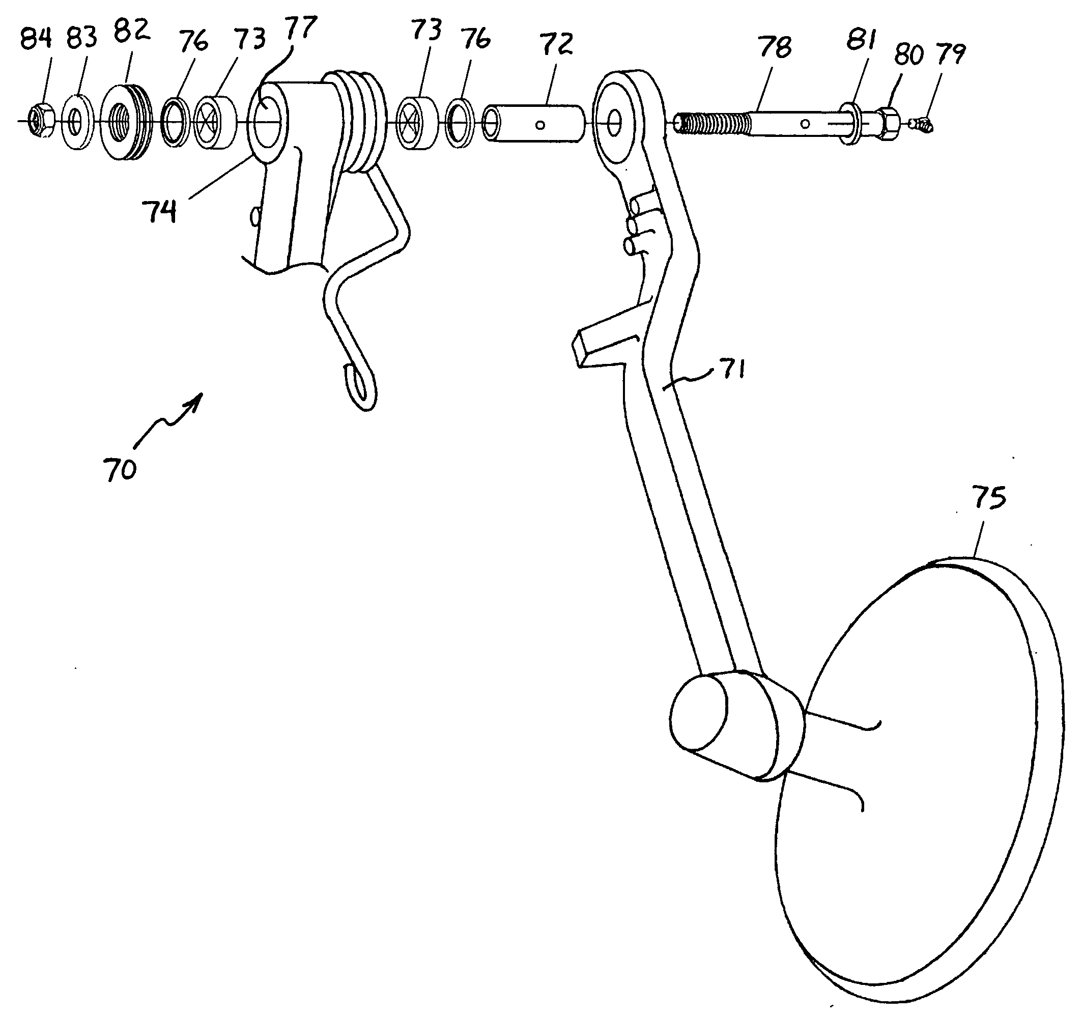
[0033] A closing wheel pivot arm assembly 70 according to the invention is shown in FIG. 6 in conjunction with a closing wheel pivot arm 71 having a bolted pivot bushing 72. In this embodiment, the clearance between the pivot bushing 72 or pivot pin with the sleeve bearings 73 was reduced to 0.001-0.002 inch (as compared to 0.007-0.008 inch clearance in the original design). This close fit almost always requires the sleeve bearings 73 to be reamed after they are installed in the bearing housing 74. This is unusual but quite manageable for farmer installed repairs.

[0034] The close fit between the outer surface of the pivot bushing 72 and the inner surface of the sleeve bearings 73 reduces impact loading and thereby reduces wear. The close fit also improves the performance of the drill by forcing the closing wheel 75 to track properly and by reducing the bounce of the closing wheel 75 significantly.

[0035] The close fit also facilitates the use of seals 76 on each side of the bearing ...

second embodiment

[0047] A pivot arm assembly 90 according to the Applicants's invention is shown in FIG. 7. This pivot arm assembly 90 is similar to that shown in FIG. 6, except that the pivot pin 91 is welded to the closing wheel arm 92 instead of using a removable bolt and pivot bushing. Thus, a repair kit for this pivot arm assembly 90 can be used with the conventional closing wheel arm pivot assembly 20 having a welded pivot pin as shown in FIG. 2. The various components having the same structure and function as those in FIG. 6 are given the same reference numerals in FIG. 7.

[0048] Installation of the pivot arm repair kit for the pivot arm assembly 90 shown in FIG. 7 is similar to the above-described installation of the repair kit for the pivot arm assembly 70 shown in FIG. 6. However, the old pivot pin is removed from the closing wheel arm 92 by grinding the welded end of the pivot pin flush and then pressing the old pivot pin through the closing wheel arm 92. A new pivot pin 91 is installed in...


PUM


Abstract

A pivot assembly for attaching a closing wheel arm to a bearing housing of a no-till drill has a pair of sleeve bearings, a pair of seals, and a pivot bushing or pivot pin that extends through the sleeve bearings and seals. The sleeve bearings are press fit into opposite ends of a bore of the bearing housing and have grooves formed across bearing surfaces thereof for grease to flow to outer ends of the bearings. The seals are also press fit into the opposite ends of the bearing housing bore. The pivot bushing or pivot pin is installed into the sleeve bearings with an outer surface thereof providing a close-running fit with the bearing surfaces of the sleeve bearings. The close-running fit has a clearance within the range of 0.001 to 0.002 inch and can be provided by passing a reamer through the inner bore of the sleeve bearings.

Description

RELATED APPLICATIONS [0001] This application claims the benefit of the Applicant's provisional patent Application No. 60 / 505,712 filed on Sep. 22, 2003.BACKGROUND OF THE INVENTION [0002] 1. Field of the Invention [0003] The present invention relates generally to pivot assemblies for agricultural planters and grain drills. In particular, the present invention relates to improved pivot assemblies for mounting closing wheel arms to no-till grain drills, and more particularly to a closing wheel arm pivot repair kit for mounting a closing wheel arm equipped with sleeve bearings to a no-till grain drill. [0004] 2. Description of the Prior Art [0005] In 1988, John Deere introduced its Model 750 no-till drill. The primary components of the individual row units are: (1) a single disk furrow opener; (2) a gauge wheel that carries the row unit and permits the planting depth to be adjusted; (3) a means of dropping seed through a tube and boot to be dropped into the furrow; (4) a press wheel tha...

Claims


Application Information

Patent Timeline
Patent Type & Authority Applications(United States)
IPC IPC(8): A01B71/04A01C5/06
CPCA01C5/066A01B71/04
Inventor KESTER, PHILIP C.
Owner KESTER PHILIP C
Learn More