[0008] The present invention was developed in order to solve the above-described problem. It is therefore an object of the invention to provide an absolute encoder capable of accurately measuring an absolute value of the rotating angle of the rotation axis with a simplified construction.
[0011] Also, a
photodetector composed so as to function as a profile sensor with respect to two directions in the two-dimensional array is used to detect measuring light passed through the two openings, respectively, whereby it is possible to preferably and accurately detect a change in the positional relationship of the above-described two openings. And, by using the rotating plate in which two openings are formed and the two-dimensional
photodetector, an absolute encoder capable of accurately measuring the absolute value of the rotating angle of the rotation axis with a simplified construction can be achieved.
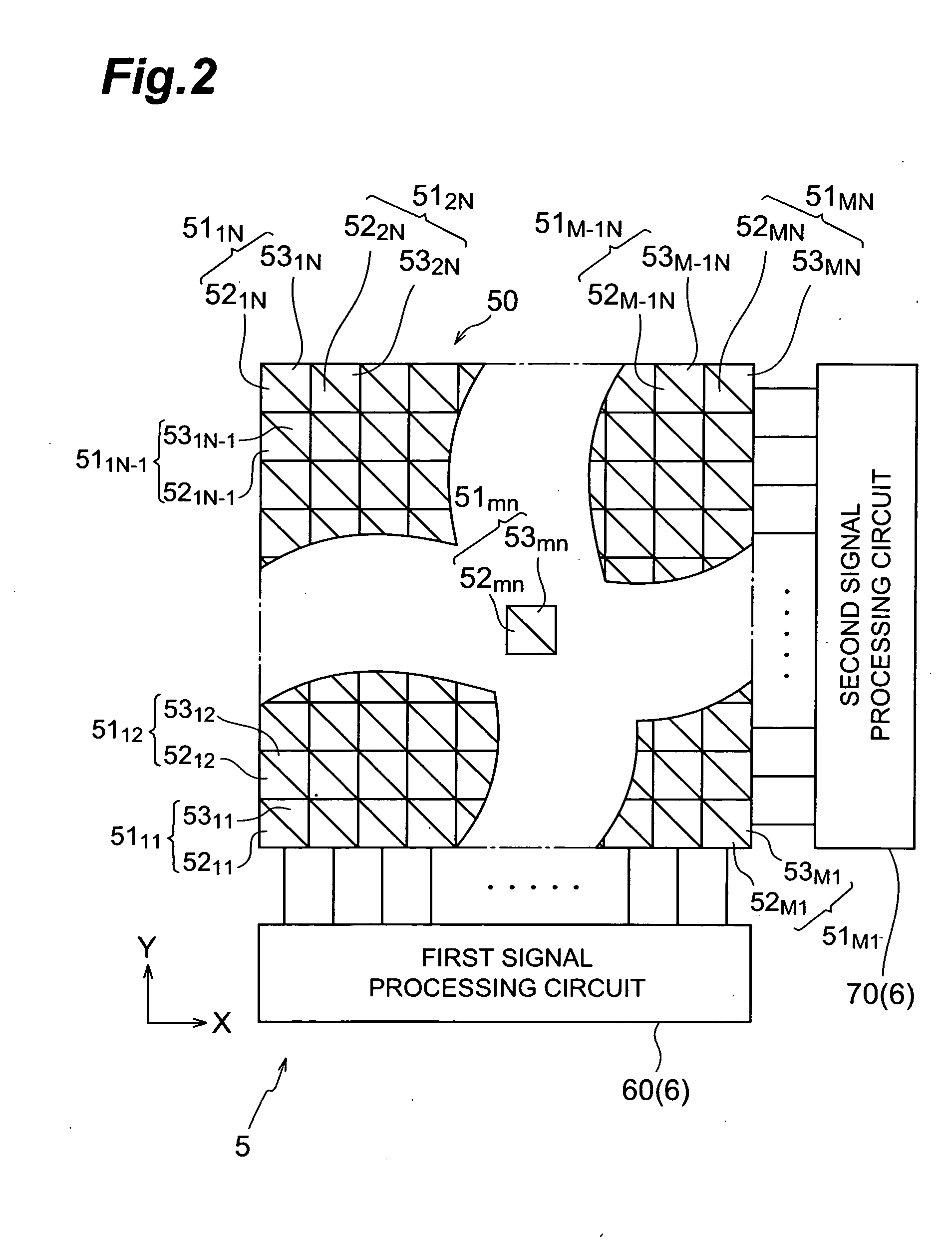
[0013] In such a photodetector, light made incident into one pixel is detected by a plurality of photosensitive portions that compose the pixel, respectively. And, since the photosensitive portions at one side are electrically connected to each other over a plurality of pixels arrayed in the first direction, current output from the photosensitive portion at one side is sent in the first direction. Also, since the photosensitive portions at the other side are electrically connected to each other over a plurality of pixels arrayed in the second direction, current output from the photosensitive portion at the other side is sent in the second direction. Therefore, a two-dimensional profile sensor capable of independently obtaining the
light intensity profile in the first direction and the
light intensity profile in the second direction, respectively, can be composed. As a result, by a remarkably simplified construction in which a plurality of photosensitive portions are provided in one pixel, it is possible to detect the two-dimensional position of measuring light passed through the two openings, respectively, at a high speed.
[0015] Also, the encoder may be configured in that the angle calculating means calculates the absolute value of the rotating angle of the rotation axis with reference to an angle calculating table showing a matching relationship between the correlation between the first detected position and the second detected position and the absolute value of the rotating angle of the rotation axis. Thus, by preparing a table (ROM table) in which the correlation of two detected positions corresponding to the positional relationship of two openings of the rotating plate is matched to the absolute values of the rotating angles in advance, it is possible to accurately calculate the rotating angle from a result of detection of measuring light in the photodetector at a high speed.
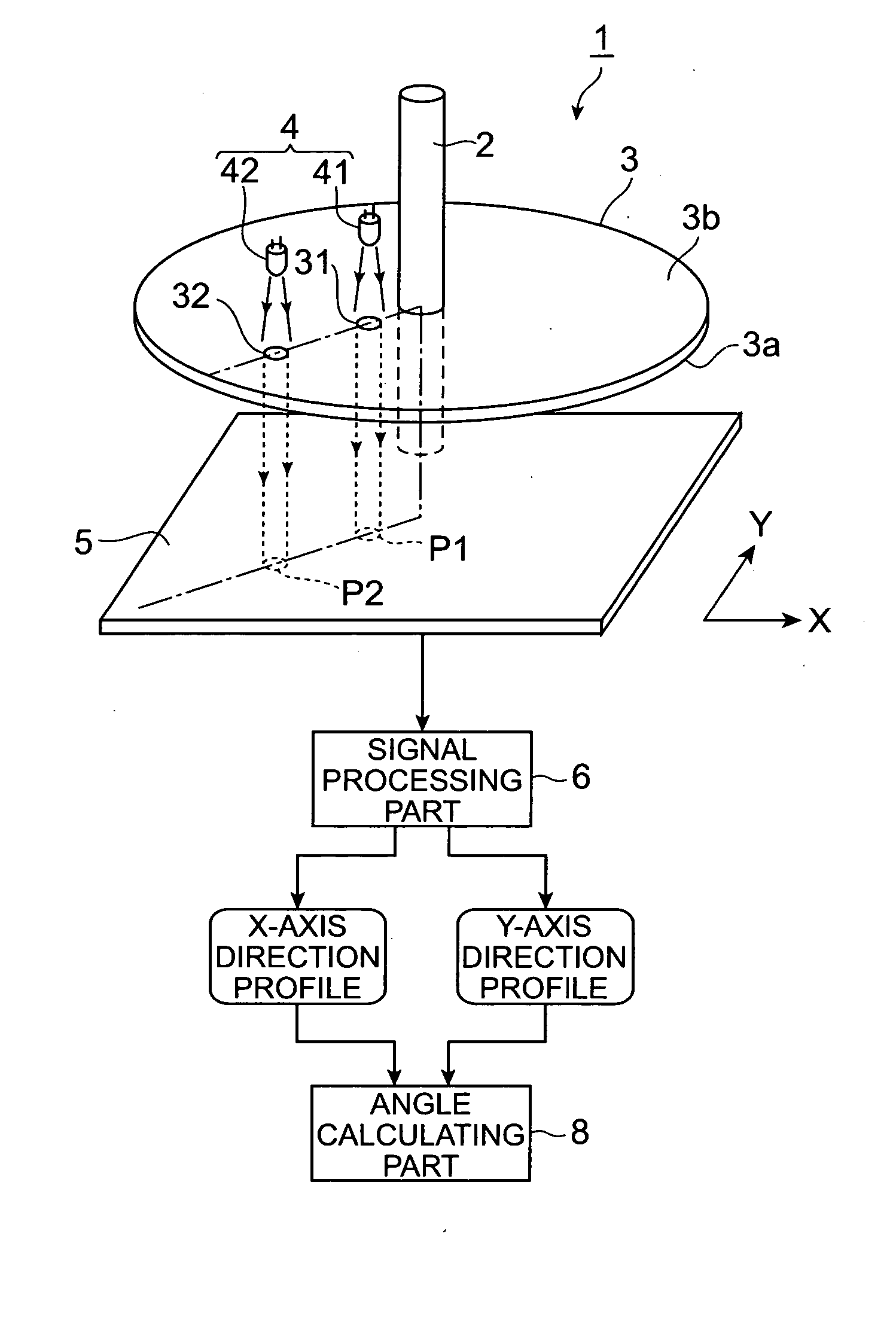
[0016] In addition, it is preferable that the light supplying means is provided with a
first light source provided so as to face the photosensitive area of the photodetector with the first opening of the rotating plate placed therebetween, and a second
light source provided so as to face the photosensitive area of the photodetector with the second opening placed therebetween. Furthermore, in this case, if the
first light source and the second
light source supply measuring light under supplying conditions differing from each other, it is possible to easily identify the first detected position in the photodetector corresponding to the first opening and the second detected position corresponding to the second opening. Or, the light supplying means may be composed of a single light source or a combination of light source and reflecting optical
system.
[0018] In addition, the rotating plate may have a third opening formed in a prescribed positional relation to the first opening and the second opening, and the angle calculating means may be composed so that the absolute value of the rotating angle of the rotating axis is calculated based on a correlation between the first detected position, the second detected position, and a third detected position where the measuring light component passed through the third opening of the rotating plate is detected by the photosensitive area of the photodetector. By using three openings as in the above, it is possible to improve the measurement accuracy of the absolute value of the rotating angle. In this case, it is preferable that the third opening of the rotating plate is formed at a prescribed position excepting on the straight line connecting the first opening and the second opening. Further, in such a composition in which three openings are employed, it is preferable that the light supplying means is provided with the
first light source fixed so as to face the photosensitive area of the photodetector with the first opening of the rotating plate placed therebetween, the second light source fixed so as to face the photosensitive area of the photodetector with the second opening placed therebetween, and the third light source fixed so as to face the photosensitive area of the photodetector with the third opening placed therebetween. Still further, in this case, if the first through third light sources supply measuring light under supplying conditions differing from each other, it becomes possible to easily identify the first through third detected positions. Or, the light supplying means may be composed of a single light source or a combination of light source and reflecting optical
system.

