Suspension apparatus for a vehicle and vehicle including same

a technology for suspension apparatus and vehicles, applied in resilient suspensions, interconnection systems, vehicle components, etc., can solve the problems of deteriorating flexibility of design and apparent disadvantages of conventional systems, and achieve the effects of simplifying the shape of suspension arms, reducing costs, and increasing design flexibility

Inactive Publication Date: 2005-04-07
HONDA MOTOR CO LTD
View PDF25 Cites 40 Cited by
  • Summary
  • Abstract
  • Description
  • Claims
  • Application Information

AI Technical Summary

Benefits of technology

[0009] An object of the invention is to reduce the cost and to increase design flexibility of a suspension arm for a vehicle suspension system by simplifying the shape of the suspension arm without particularly requiring increase in rigidity of the suspension arm by including a stabilizer bar in a suspension system of a vehicle.

Problems solved by technology

A disadvantage of this conventional system becomes apparent when the vehicle body rolls.
Further, the shape of the upper suspension arm 202 is limited by these requirements so that the flexibility of designing deteriorates.

Method used


Image

  • Suspension apparatus for a vehicle and vehicle including same
  • Suspension apparatus for a vehicle and vehicle including same
  • Suspension apparatus for a vehicle and vehicle including same

Examples


Embodiment Construction

[0029] A selected illustrative embodiment of the invention will be described below, with reference to the attached drawings. The disclosure hereof includes the best mode contemplated by the inventors for carrying out the invention.

[0030] Vehicle Overview

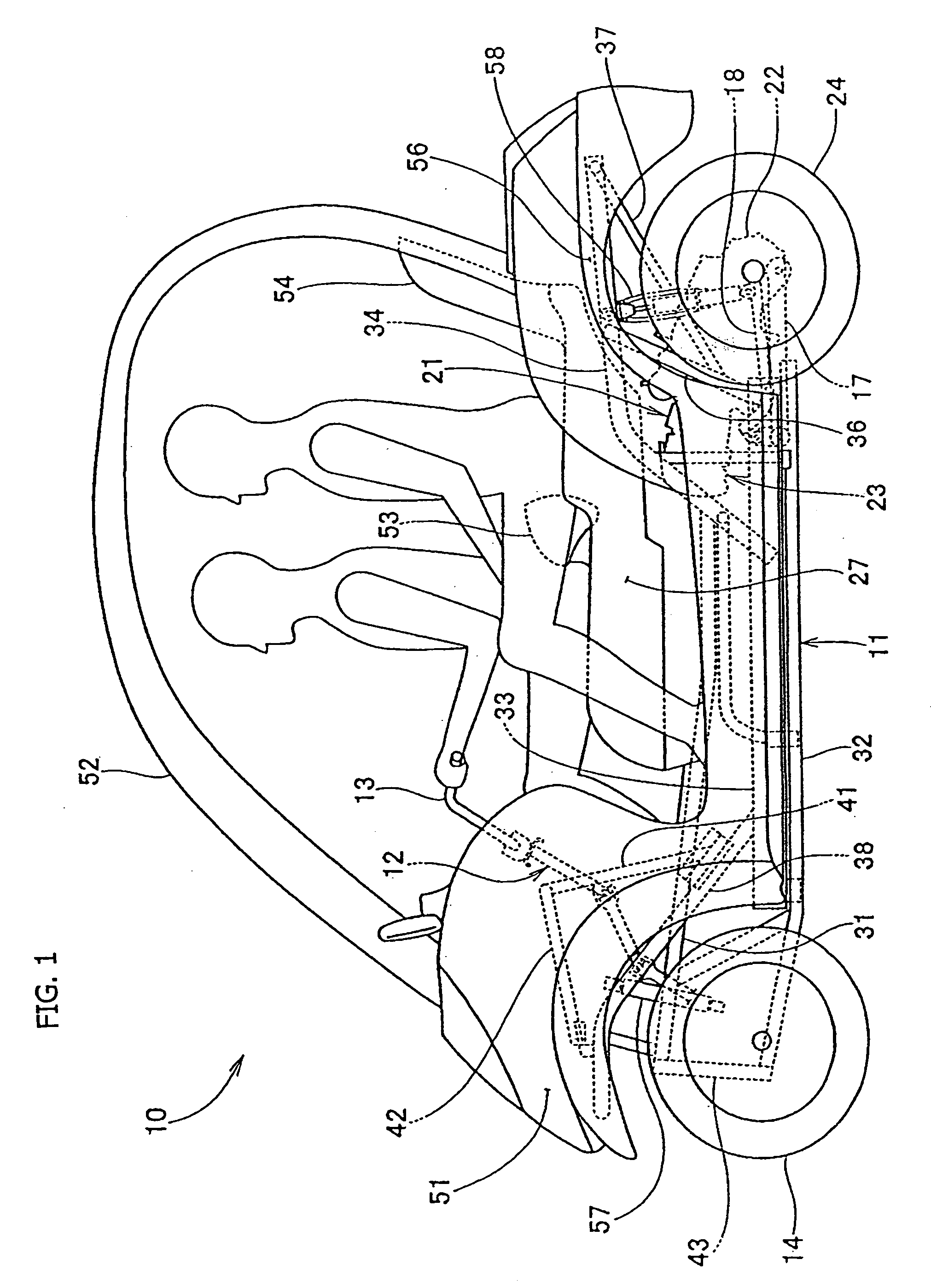
[0031]FIG. 1 is a side view of a vehicle 10 incorpoating a suspension system according to a selected illustrative embodiment of the invention. The vehicle 10 is a four-wheeled vehicle designed for carrying two persons, and includes a vehicle body frame 11. A steering shaft 12 is attached to a front portion of the vehicle body frame 11, and a handlebar 13 is attached to the top of the steering shaft 12 to permit steering of the right and left front wheels 14 and 15 of the vehicle (only the front wheel 14 on the left side is shown).

[0032] A powertrain unit 23, including an engine 21 and a transmission 22 attached to the rear portion of the engine 21, is attached to the rear portion of the vehicle body frame 11 via supporting arms 17...


PUM


Abstract

In a vehicle suspension system, suspension arms are attached to the right and left sides of a vehicle body frame, a knuckle is attached to the ends of the suspension arms, a front shock absorber is provided between the vehicle body frame and the suspension arm on each side of the frame, and a stabilizer bar is provided extending between the right and left suspension arms. The stabilizer bar extends between rigid right and left shock support members provided on the ends of the suspension arms. The rigid shock support members are coupled to the knuckle, and also support the lower ends of the front shock absorbers. Costs of the suspension system are reduced by providing the rigid support member in combination with the stabilizer bar, since the shape of a suspension arm can be simplified without requiring particular increase in rigidity.

Description

CROSS-REFERENCE TO RELATED APPLICATIONS [0001] The present invention claims priority under 35 USC 119 based on Japanese patent application No. 2003-340118, filed Sep. 30, 2003. BACKGROUND OF THE INVENTION [0002] 1. Field of the Invention [0003] The present invention relates to vehicle suspension systems. More particularly, the present invention relates to the structure and installation of a stabilizer bar for a vehicle suspension system. [0004] 2. Description of the Background Art [0005] A structure in which a stabilizer bar is provided in a wishbone-type suspension system between right and left upper suspension arms is known. For example, such a suspension system is described in Japanese Patent Laid-open No. Hei 3-213414. [0006]FIG. 2 of Japanese Patent Laid-open No. Hei 3-213414 has been reproduced herein as FIG. 8. It will be described using newly assigned reference numerals. FIG. 8 is an explanatory diagram showing a conventional structure of a stabilizer bar within a suspension...

Claims


Application Information

Patent Timeline
Patent Type & Authority Applications(United States)
IPC IPC(8): B60G1/00B60G3/20B60G7/00B60G21/055
CPCB60G3/20B60G7/001B60G21/0551B60G2200/144B60G2200/44B60G2206/11B60G2204/129B60G2204/416B60G2204/422B60G2204/43B60G2204/1224
Inventor SEKI, BUNZO
Owner HONDA MOTOR CO LTD
Why Eureka
Try Eureka