Supercharge Your Innovation With Domain-Expert AI Agents!

High-definition cathode ray tube and electron gun

a cathode ray tube, high-definition technology, applied in the field of cathode ray tubes, can solve the problems of increasing brightness, reducing reliability, increasing the cost of the electron gun,

Inactive Publication Date: 2005-04-07
ALTERA CORP
View PDF6 Cites 2 Cited by
  • Summary
  • Abstract
  • Description
  • Claims
  • Application Information

AI Technical Summary

Benefits of technology

The patent describes a way to create high-definition color or monochrome displays using a CRT and electron gun. The electron beam is made up of multiple collimated sub-beams that are focused to a single spot on the screen using a main lens. The patent explains how to manufacture the electrodes to create these sub-beams using different techniques. The technical effect of this patent is to provide a more precise and accurate way to create high-definition displays using advanced technology.

Problems solved by technology

In a typical CRT, increasing brightness reduces resolution because the electron beam spot size increases at higher electron beam current levels.
In typical prior art CRTs, items (1) and (2) cannot be achieved simultaneously without changes to the electron gun design that would compromise the manufacturing tolerances, and thus increase the cost of the electron gun, and item (3) is costly and causes reduced reliability due to the increased power dissipation in the high-speed electronics.
This causes the active cathode surface area to decrease in size, which in turn decreases crossover size, and thus spot size, but it also reduces the slope of the current versus biasing voltage curve (the “drive curve”).
Increasing the voltage on the extraction electrode 204 also increases the angle at which electrons in the beam 206 leave the cathode 201, which may then require an additional focus electrode to be required in the electron gun, increasing its cost.
Although it is possible to vary the aperture diameters in the beam-forming electrodes, and to also vary the spacing of the electrodes, restricting these variations to practical values limited by manufacturing and positioning tolerance makes only moderate changes to the spot size, drive range, and maximum beam current.
In addition, the application does not teach the benefits of such a structure for reducing the drive range of the CRT.

Method used


Image

  • High-definition cathode ray tube and electron gun
  • High-definition cathode ray tube and electron gun
  • High-definition cathode ray tube and electron gun

Examples


Embodiment Construction

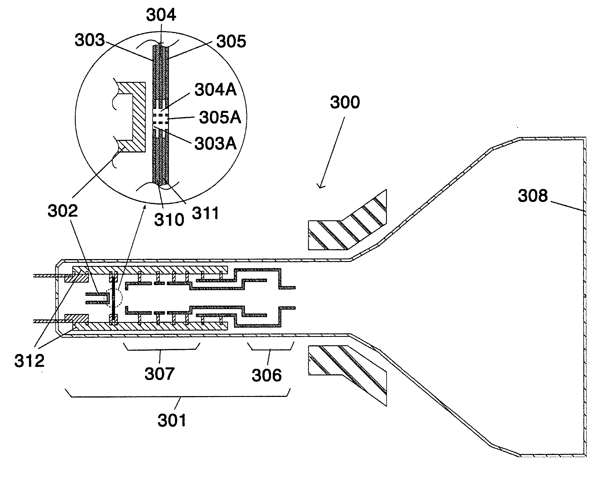
[0028]FIG. 3A illustrates a mono-beam CRT 300 of the present invention, such as may be used in a high-resolution projection or monochrome display. A mono-beam electron gun 301, having a cathode 302, a first beam-forming electrode 303, a second beam-forming electrode 304 and a third beam-forming electrode 305 is shown (refer to inset). The first and second beam-forming electrodes 303, 304 are electrically separated by an insulator 310, and the second and third beam-forming electrodes 304, 305 are electrically separated by another insulator 311. It should be understood to one skilled in the art of electron gun construction that the insulators 310, 311 may be comprised of a vacuum gap, dielectric material, polymer material, or any other electrically insulating material that is compatible with the vacuum and thermal requirements of vacuum tube production and operation.

[0029] A main lens 306 and a plurality of pre-focus electrodes 307 are disposed between the three beam-forming electrod...


PUM


Abstract

A high-definition CRT is provided having an electron gun to produce high beam current without increasing spot size and to provide lower electrical power requirements at high beam-modulation frequencies. The electron gun includes three electrodes having clusters of apertures to allow collimation of the electron beam from a cathode. The main lens is operated to focus a parallel beam of electrons on a display screen. Methods for manufacturing by mechanical or semiconductor methods are also provided.

Description

[0001] This application is related to U.S. Patent Application Publication No. US 2002 / 0089277, filed Jan. 5, 2002.BACKGROUND OF THE INVENTION [0002] 1. Field of the Invention [0003] This invention pertains to cathode ray tubes or other electronic devices employing electron beams, and particularly to those cathode ray tubes and electron guns contained therein that are used to display high-resolution imagery. [0004] 2. Discussion of Related Art [0005] The principal components of a cathode ray tube (CRT) are (FIG. 1): an envelope 101, an electron gun 102 (which has a “beam-forming region”103 and a main lens region 104), a deflection yoke 105, and a display screen 106. A typical prior-art electron gun beam-forming region 103 consists of a cathode 107, a first electrode 108 (often called a “Wehnelt” or “suppressorelectrode) with an aperture 109 and a second electrode 110 (often called an “extractor” electrode) with a coaligned aperture 111. The primary function of the beam-forming regi...

Claims


Application Information

Patent Timeline
Patent Type & Authority Applications(United States)
IPC IPC(8): H01J9/18H01J29/48
CPCH01J9/18H01J2229/4844H01J29/488
Inventor SKUPIEN, THOMAS A.ZOLLARS, BYRON G.
Owner ALTERA CORP
Features
  • R&D
  • Intellectual Property
  • Life Sciences
  • Materials
  • Tech Scout
  • Unparalleled Data Quality
  • Higher Quality Content
  • 60% Fewer Hallucinations
Learn More