Current monitoring/control circuit

Inactive Publication Date: 2005-04-07
NORTHROP GRUMMAN SYST CORP
View PDF8 Cites 8 Cited by
  • Summary
  • Abstract
  • Description
  • Claims
  • Application Information

AI Technical Summary

Benefits of technology

The output of the feedback amplifier drives the gate terminal of the FET more positive if the gate winding voltage is lower than the reference voltage. When the gate winding voltage becomes equal to the reference voltage, the feedback circuit is stable, and the gate winding current is set to the desired zero current operating point. The bias current is adjusted in response to changes in the current flow through the

Problems solved by technology

Eddy currents are induced as the flux changes, causing added loss.
Thus, the greater the control current, the greater the imbalance between the gate windings, and the larger the

Method used


Image

  • Current monitoring/control circuit
  • Current monitoring/control circuit
  • Current monitoring/control circuit

Examples


Embodiment Construction

The following discussion of the embodiments of the invention directed to a current monitoring and control circuit employing a magnetic amplifier and a feedback circuit is merely exemplary in nature, and is in no way intended to limit the invention or its applications or uses.

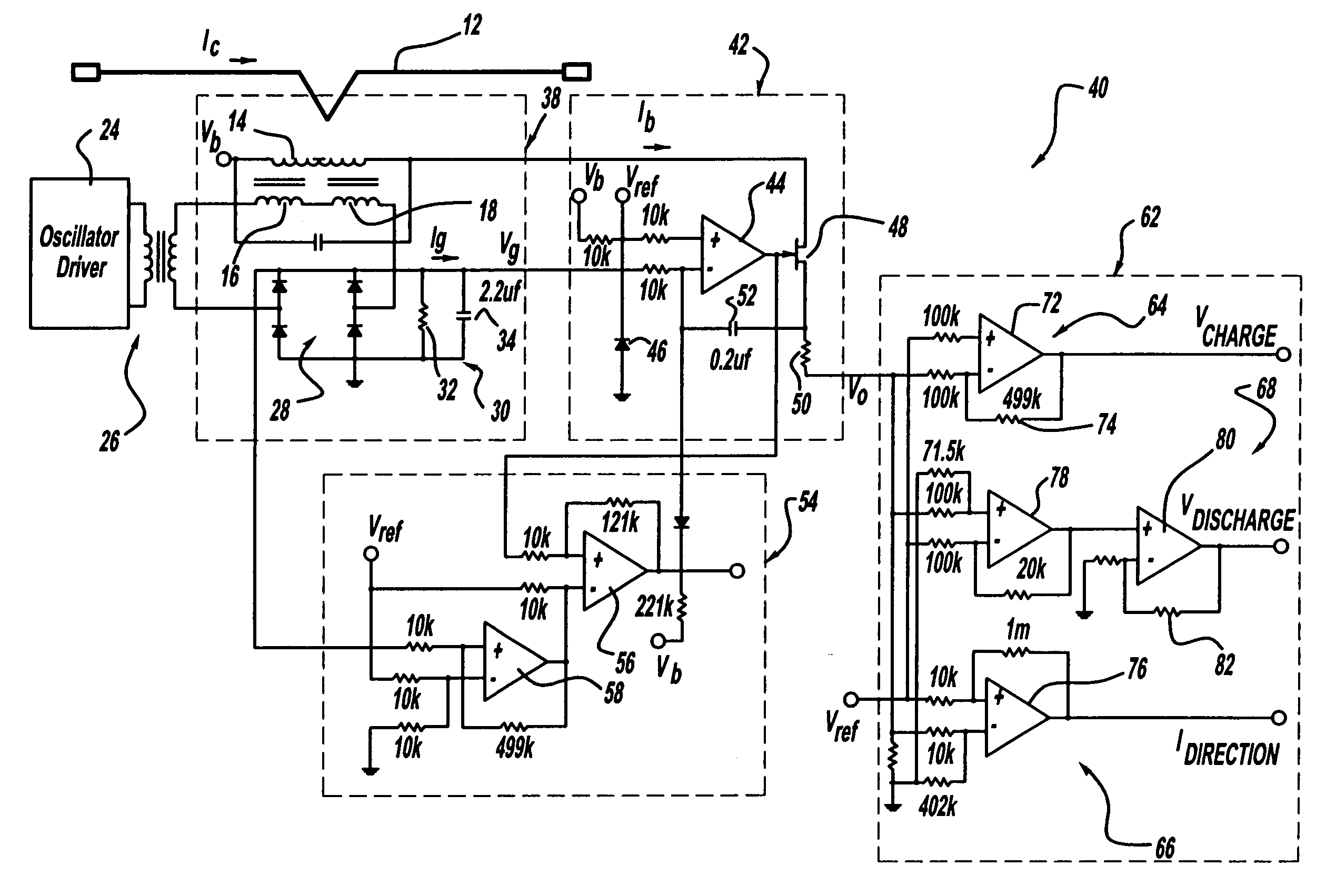
FIG. 4 is a schematic diagram of a current monitoring and control circuit 40, according to an embodiment of the present invention, that includes a magnetic amplifier 38. The elements of the magnetic amplifier 38 are the same as the amplifier 10 discussed above and are identified by the same reference numeral. The control circuit 40 includes an active feedback circuit 42 that sets the operating current of the control circuit 40 so that it remains at a fixed operating point defined by a reference voltage Vref, as will be discussed in detail below. By adding the feedback circuit 42, the full operating range of the circuit 40 is not limited by the range of the amplifier 38, and can be expanded to the limit of bias...


PUM


Abstract

A current control circuit that employs a magnetic amplifier and an active feedback circuit. The feedback circuit establishes the effective operating current of the amplifier at a fixed point. The magnetic amplifier includes a pair of oppositely wound gate windings, a bias winding and a control winding. The gate windings are driven by an oscillator driver that generates a gate winding current and a gate winding voltage. A reference voltage and the gate winding voltage are applied to a feedback amplifier and the feedback circuit. When the gate winding voltage becomes equal to the reference voltage, the feedback circuit is stable and the gate winding current is set to a desired zero current operating point.

Description

BACKGROUND OF THE INVENTION 1. Field of the Invention This invention relates generally to a current monitoring and control circuit and, more particularly, to a current monitoring and control circuit that employs a magnetic amplifier and a feedback circuit, where the amplifier circuit provides a bias current that causes the feedback circuit to operate the amplifier at a predetermined point to improve output linearity. 2. Discussion of the Related Art Saturable core reactors have been employed in the art as variable impedance devices to detect direct current flowing in an operating circuit, while maintaining isolation between the operating circuit and an output circuit. A saturable reactor is a magnetic circuit element including a coil of wire wound around a magnetic core. The magnetic core significantly alters the behavior of the coil by increasing its magnetic flux and by confining most of the flux to the core. Magnetic flux density (B) is a function of applied magnet motive for...

Claims


Application Information

Patent Timeline
IPC IPC(8): G01R15/18G01R19/00
CPCG01R19/003G01R15/183
Inventor BAXTER, DONALD L.WHEELER, KENNETH B.NGUYEN, DAVID C.
Owner NORTHROP GRUMMAN SYST CORP
Why Eureka
Try Eureka