Micro-adjustable boring bar

a boring bar and micro-adjustable technology, applied in the direction of turning machine accessories, manufacturing tools, transportation and packaging, etc., can solve the problems of cost to the manufacturer, achieve excellent practicality, prevent the cutting bit from striking, and simplify the boring hole procedure greatly.

Inactive Publication Date: 2005-04-07
CHANG
View PDF29 Cites 20 Cited by
  • Summary
  • Abstract
  • Description
  • Claims
  • Application Information

AI Technical Summary

Benefits of technology

[0007] By means of the micro-eccentric bore, turning the boring bar shaft an angle around the rotation axis can change the distance from the tip end of the cutter edge to the rotation axis to correct the size of the boring hole in positive or negative; on the other hand, whatever the boring bar shaft is turned in clockwise or anticlockwise, the dynamic balance of said assembled boring bar set is constant, in the other word, the dynamic balance of the boring bar shaft will not be changed, therefore as micro-adjusting the size of boring hole the dynamic balance will not be reset, so the present invention has excellent practicality, and simplifies the procedure of boring hole greatly. More specially, a pair of limited points is set upon the adapter, even if the boring bar shaft has not been fastened yet when the machine is cut on, the boring bar shaft is automatically turned to the minimal size position, thereby preventing the cutting bit form striking on the boring hole rim without any anxiety about damaging boring bar, further to protect the cutting bit under the boring bar shaft unlocked situation.

Problems solved by technology

Additionally, said micro-adjustable boring bar 10 costs about USD$600, especially to multiple holes processing, a relative number of the micro-adjustable boring bars have to be prepared; it is a huge cost to the manufacturer, so it is another shortcoming.

Method used


Image

  • Micro-adjustable boring bar
  • Micro-adjustable boring bar
  • Micro-adjustable boring bar

Examples


Embodiment Construction

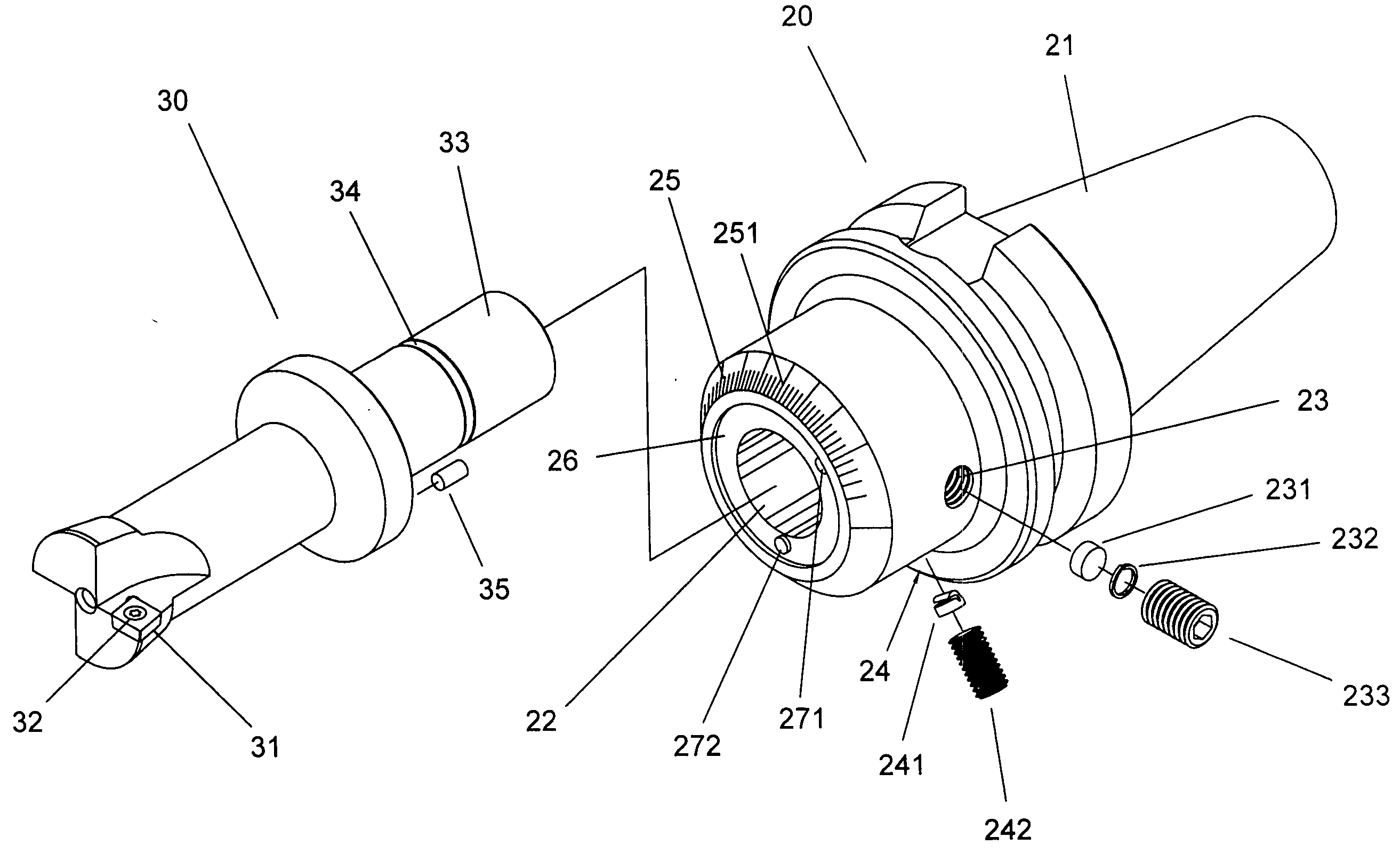
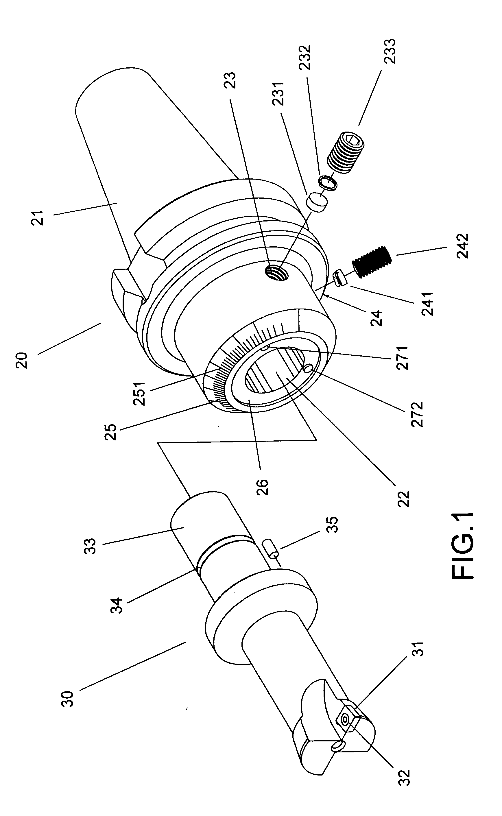
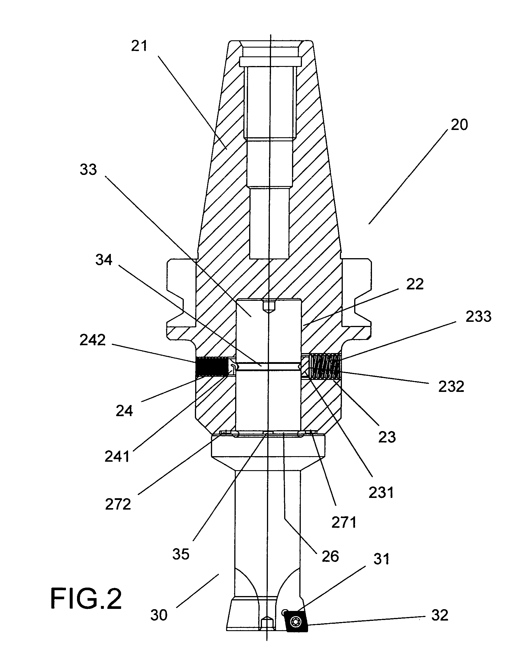
[0019] Referring to FIG. 1 to FIG. 3, a micro-adjustable boring bar provided by the present invention includes an adapter 20 and a boring bar body 30. Wherein:

[0020] Said adapter 20 has a BT40 tapering spindle 21 at one end and a micro-eccentric bore 22 at another end, wherein the offsetting is about 0.1 mm, and a securing threaded hole 23 is set upon at the opposite side of the eccentricity side for sequentially holding a limiting block 231 and an elastic trip latching into the thread of the threaded hole 23 for preventing the limiting block 231 for falling out, and a screw 233 securing in from the outside, and a locating threaded hole 24 is built upon the side of said micro-eccentric bore 22 and kept an angle with said securing threaded hole 23 for holding an elastic locating block 241 and a screw 241 securing in, and one open end of said adapter 20 is appeared into a frustum with a pyramidal face 25, and a graduations 251 are built on it, a circular recess 26 is set upon the fro...


PUM

PropertyMeasurementUnit
sizeaaaaaaaaaa
sizeaaaaaaaaaa
sizeaaaaaaaaaa

Abstract

The present invention provides a micro-adjustable boring bar, which includes boring bar body and an adapter, wherein said adapter has a micro-eccentric bore set upon one end for plugging in the boring bar body with the pivoting shaft, and a V-shaped ring groove is built upon the proper position of said pivoting shaft of the boring bar body, coordinating to said V-shaped ring groove, the adapter has a securing threaded hole and a locating threaded hole built on, therein said securing threaded hole is built on opposite side of the eccentric side of the micro-adjustment bore, said locating threaded hole is used to hold an elastic limiting block in, by securing the screw in, the elastic limiting block can generate an upward elastic force to push the pivoting shaft of boring bar body upward to touch against the adapter more tightly and improve the combined assembly's rigidity; by means of the eccentric design, turning the boring bar body in the micro-adjustment bore of the adapter can move the tip end of the cutter tool to change the boring size of the hole in positive or negative for increasing or decreasing the size of boring hole, and whatever turning the boring bar body in which direction for micro-adjusting, the dynamic balance will be kept in constant without any resetting dynamic balance.

Description

BACKGROUND OF THE INVENTION [0001] 1. Field of the Invention [0002] The present invention relates to a micro-adjustable boring bar, and refers more specifically to the micro-adjusting mechanism based on the eccentric principle, thereby composite a micro-adjustable boring bar with high rigid, good balance as with along the fine adjustment of the boring cutter, on the other hand, some safety devices attached on it for preventing the adjustment from overpass safety limitation, and the boring cutter from damage occurred by loosing the fastening screw. [0003] 2. Description of Prior Art [0004] In accordance with the conventional micro-adjustable boring bar 10, as shown in FIG. 11, the fine adjustment device is comprised of a trimming screw 11, an arbor nut 12 and an arbor 13, by adjusting said trimming screw 11, the tip position of the tool bit 14 is changed further, so as to get fine adjustment of the size of bored hole, on the other hand a balance device is set upon above the fine adju...

Claims


Application Information

Patent Timeline
Patent Type & Authority Applications(United States)
IPC IPC(8): B23B29/00B23B29/034
CPCB23B29/03428Y10T408/854B23B2260/088
Inventor CHANG, HSIN-TIEN
Owner CHANG
Why Eureka
Try Eureka