Sail wing type windmill and operation method of same

a technology of sailing wing and windmill, which is applied in the direction of machines/engines, renewable energy generation, greenhouse gas reduction, etc., can solve the problems of serious improvement and damage to the structure of the sailing wing windmill, and achieve the effects of reducing engineering costs, reducing costs, and operating securely

Inactive Publication Date: 2005-04-07
CHIO CHUY NAN
View PDF5 Cites 17 Cited by
  • Summary
  • Abstract
  • Description
  • Claims
  • Application Information

AI Technical Summary

Benefits of technology

[0012] The present invention is to provide a sail wing type windmill which can work in all direction without the need of tracing the wind direction from time to time, and the windmill can be fabricated and assembled with reduced cost while it can be operated securely.
[0013] According to the present invention, a vertical shaft is provided for the windmill instead of the conventional horizontal shaft so as to reduce the engineering cost. A sail type wing blade is adopted to replace the propeller type wing blade thereby eliminating the windage loss arising from cutting the wind strata to improve energy conversion efficiency as high as possible.
[0014] A rudder is designed to turn freely about the windmill shaft by a turn table which has a twin vaned tail wing at its rear end which can automatically turn the rudder to face against the wind direction by the turn table with a concave upwardly curved lead rail. The wing blade and the lead rail is connected with a connecting rod which is movable on the lead rail with an end roller and jointed with the wing blade at its front port

Problems solved by technology

(3) A windage force produced during cutting wind by wing blades and flywheels might become overturning torque to destr

Method used


Image

  • Sail wing type windmill and operation method of same
  • Sail wing type windmill and operation method of same
  • Sail wing type windmill and operation method of same

Examples


Embodiment Construction

[0021] Hereinbelow, the preferred embodiment of the present invention will be described in detail in conjunction with the accompanied drawings:

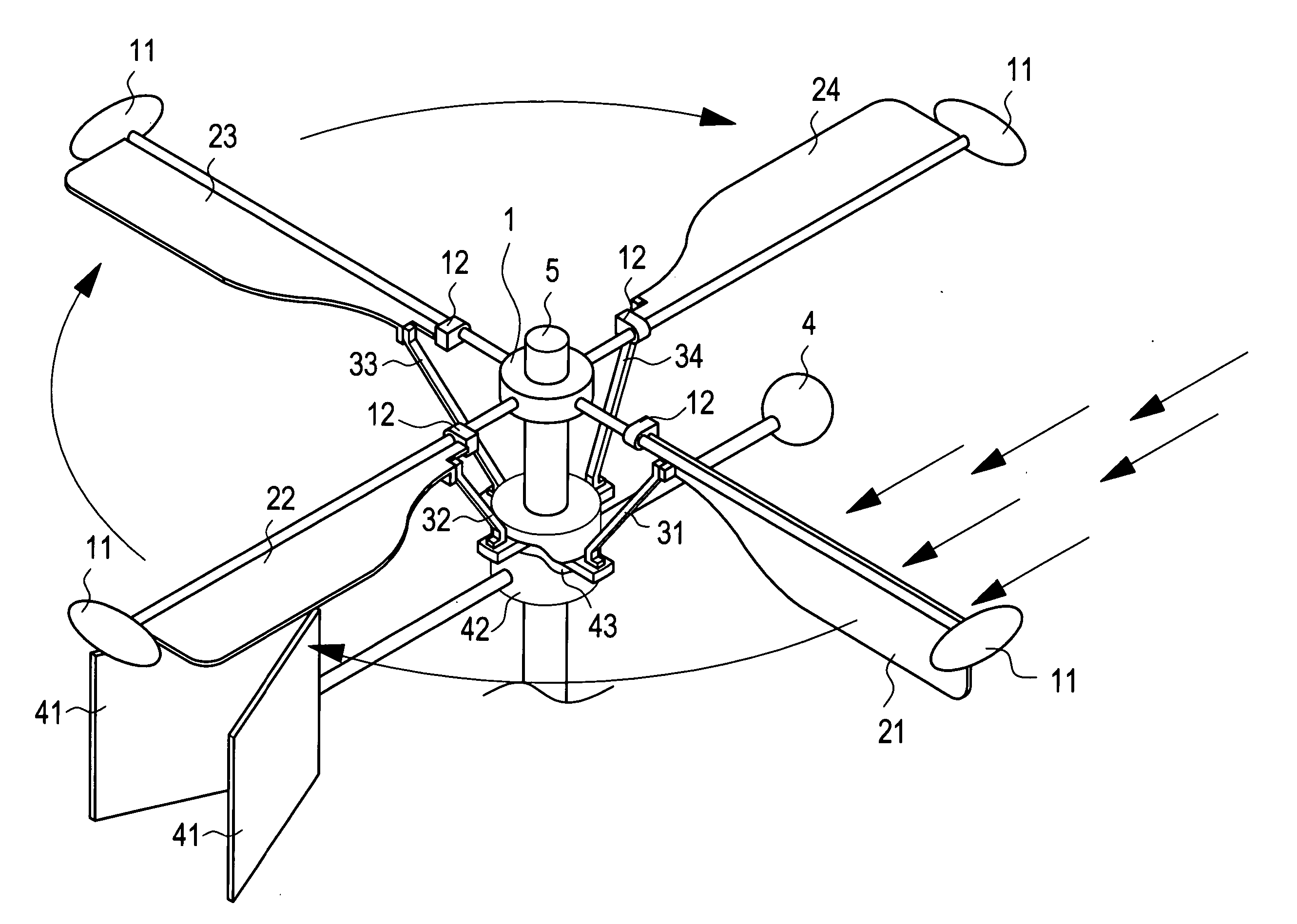
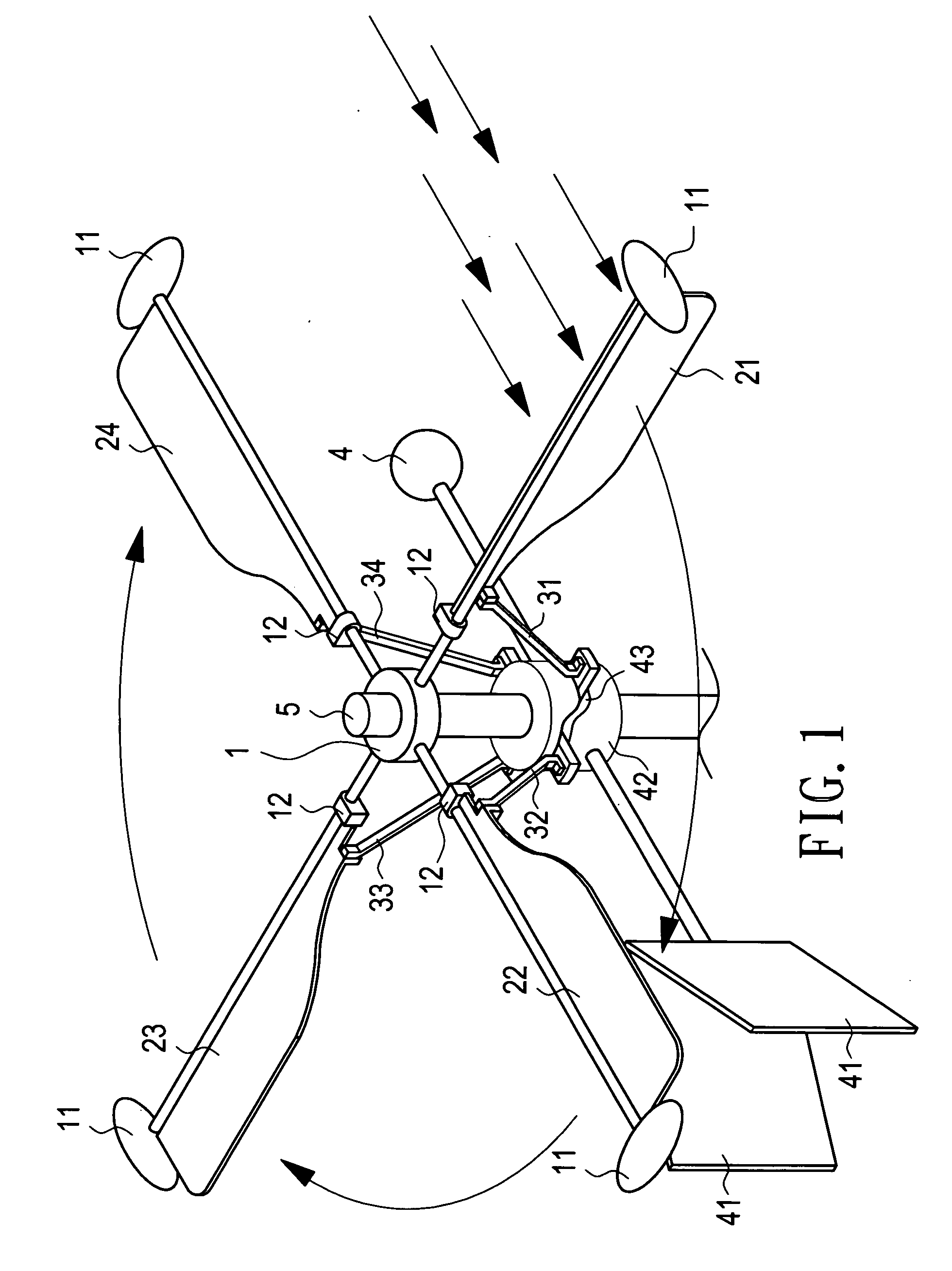
[0022] Referring to FIG. 1, in the perspective view of the present invention, a shaft 5 of the windmill is vertically erected to be conjoined with the rotating shaft of a generator. A fly wheel hub 1 is coupled to the shaft 1 and several centrifugal fly wheels 11 are radially extended from the hub 1 each with a supporting brace so that the fly wheels 11 are disposed circularly. Each fly wheel 11 is configurated into a stream saucer (or spherical) form so as to reduce the windage resistance. Each fly wheel 11 is filled with a weighty substance to improve its fly wheel effect.

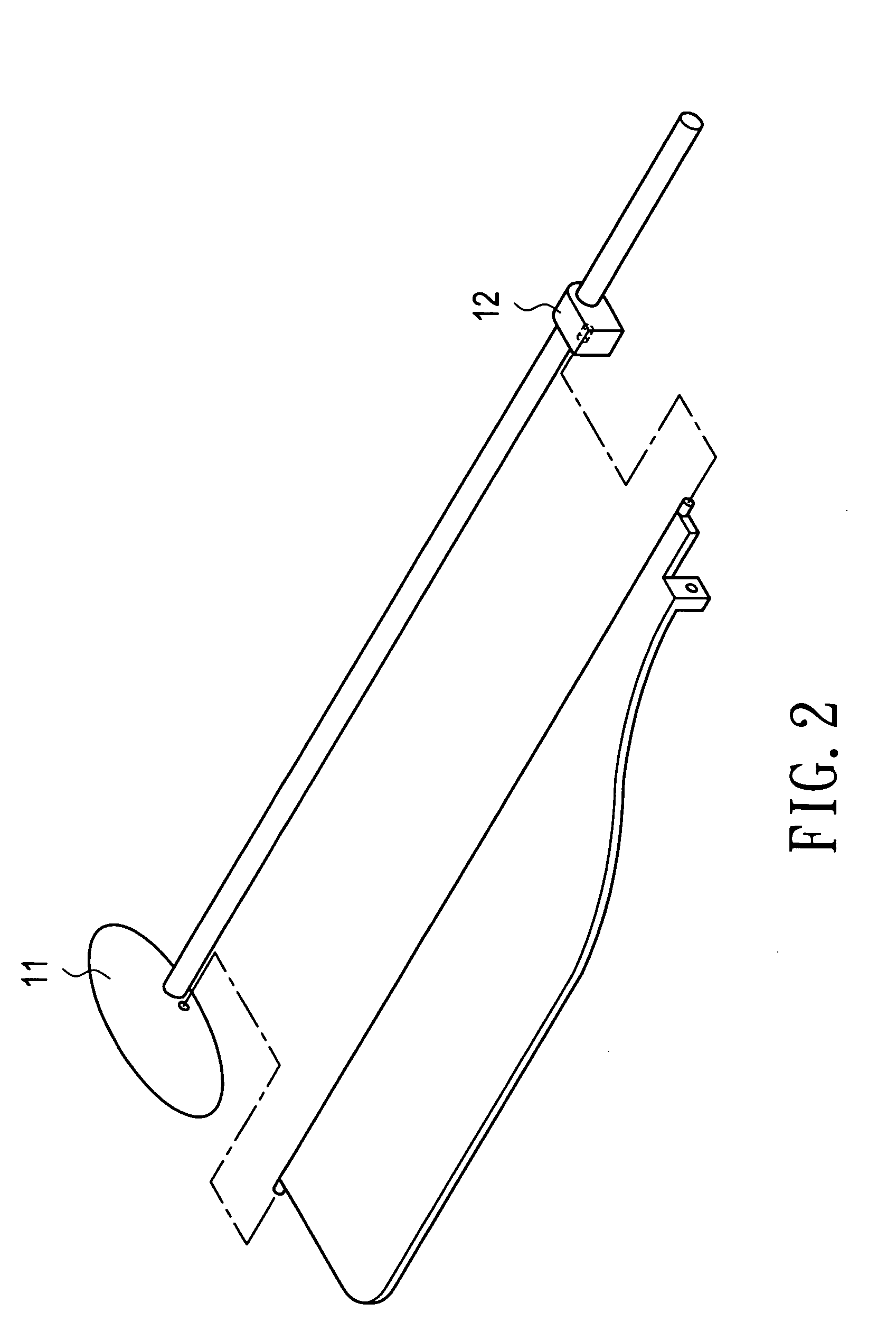
[0023] Referring to FIG. 2 together with FIG. 1, each supporting brace of the fly wheel 11 is provided with a jaw 12 proximate to the hub 1 to hook each of fan blades 21, 22, 23, 24 onto a recess hole formed onto the brace so that the fan blades 21, 22, 23, 24 are rotata...


PUM


Abstract

A wing type windmill is provided with a rudder able to constantly facing to the wind direction controlled by turn table having a twin vaned tail wing and a concave upwardly curved lead rail. The vertically shafted windmill has several sail type wing blades each of them can develop or shrink its surface to face or offset the wind direction following the up and down motion of the end roller of the connecting rod along the lead rail. The produced rotating torque by individual wing blade is imparted to a centrifugal fly wheel hub from time to time and this non-uniform torque and unstable rotating speed of the windmill is unified and governed stably by the fly wheel effect of a plurality of fly wheels filled with a weighty substance.

Description

BACKGROUND OF THE INVENTION [0001] 1. Field of the Invention [0002] The present invention relates to a sail wing type windmill and operation method of same, and more particularly, to a sail wing type windmill to convert the wind power into the mechanical power, and its operation method. [0003] 2. Description of the Prior Art [0004] It is well known that the windmill has been utilized to convert the wind power into electric power for thousands of years, and conversion of wind power to electricity has been paid great attention by the whole word due to serious energy shortage which is possible to come before long. [0005] In a typical windmill power station, a horizontal shaft windmill composed of three or four vaned wing with fly wheels is coupled to the generator shaft to drive the generator with the windmill. The rotating power of the windmill comes from upwards and downwards wind flow attacking the wing blades of the windmill, whereas the flywheel is for storing the kinetic energy a...

Claims


Application Information

Patent Timeline
IPC IPC(8): F03D3/00F03D3/06F03D7/00F03D7/06
CPCY02E10/74F03D3/068F03D9/12Y02E60/16Y02E70/30
Inventor CHIO, CHUY-NAN
Owner CHIO CHUY NAN
Why Eureka
Try Eureka