Interlocking IM nails with outer screw

a technology of im nails and screws, applied in the field of interlocking im nails with outer screws, can solve the problems of increasing the fixation in the cortical bone, not helping the screw-nail interface, and loss of reduction, so as to achieve stable fixation and eliminate the play of the screw-nail interface

Inactive Publication Date: 2005-04-07
SEMET ELLIOT CHARLES
View PDF7 Cites 22 Cited by
  • Summary
  • Abstract
  • Description
  • Claims
  • Application Information

AI Technical Summary

Benefits of technology

[0033] This invention provides for a new method for locking Intramedullary Nails (IM Nails) with headless screws for performing interlocking with the IM Nail. The headless screw is over drilled with a canulated drill. A subsequent, outer screw is placed such that it encapsulates this headless screw. The outer screw engages threads on the nail, locking the outer screw to the nail. This method and design eliminates play in the screw-nail interface and result in a more stable form of fixation. The headless screw may also have a sleeve on the outer end which will aid in centering of the IM Nail. The outer screw may also be placed from the contra lateral side where the anatomy will allow it.

Problems solved by technology

One of the current method of interlocking IM Nails is to solely use screws, which can result in loss of reduction because of the inherent play in screw-nail interface.
A second way of interlocking IM Nails is to cap the screw at the contra lateral cortex, which increases fixation in the cortical bone; however, does not help the screw-nail interface; additionally, pressure applied by the capping on one end may cause the distal end to move out of position.
A third available way of interlocking IM Nails is to have the hole of the IM Nail lined with rubber to provide a more grippable material for the screws; however, the inherent play in rubber does not provide sufficient locking.
This product is currently not marketed; however, this would be a difficult mechanism because there are only a couple of safe zones where screws can be placed.
With the addition of 2 screws placed for fixation, it may be difficult to find safe zones.

Method used


Image

  • Interlocking IM nails with outer screw
  • Interlocking IM nails with outer screw
  • Interlocking IM nails with outer screw

Examples


Embodiment Construction

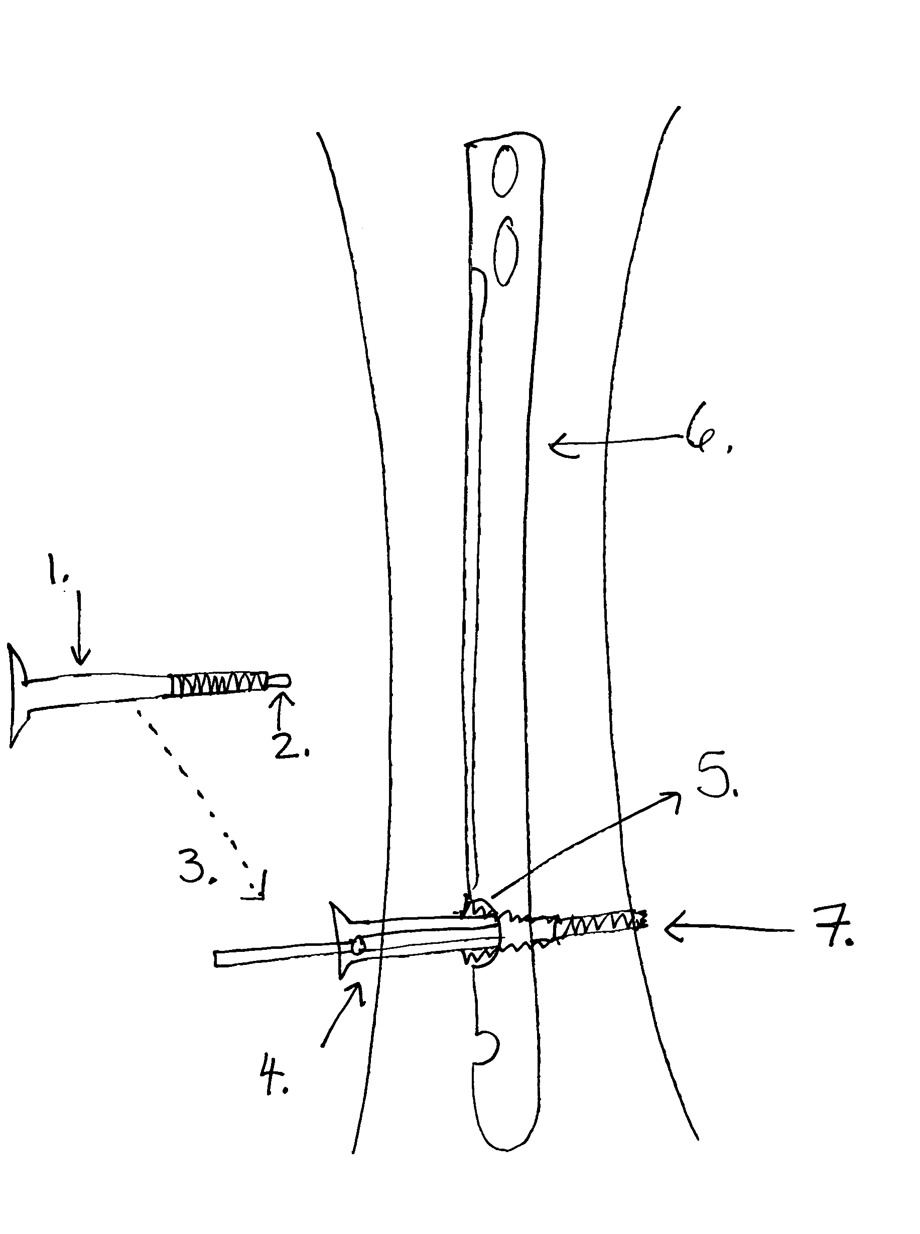
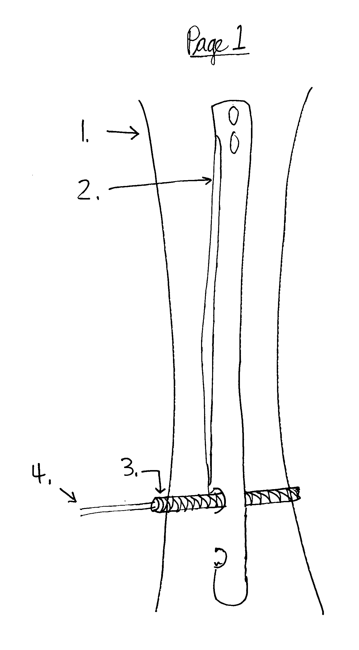
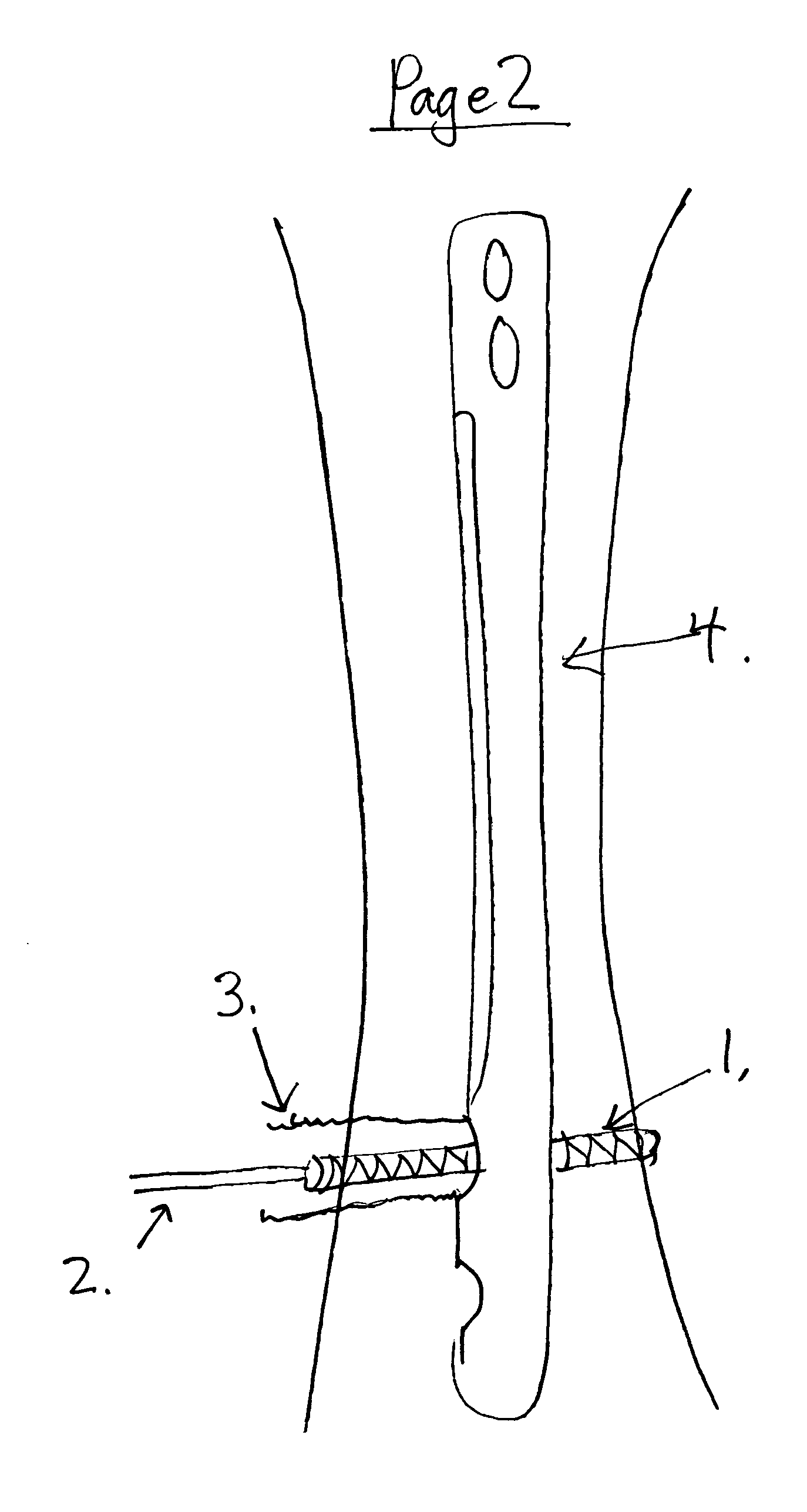
[0052] The IM Nails and screws are manufactured with cobalt-chrome, titanium or other materials for strength and durability. The current methods do not address screw-nail interface locking and can cause loss in reduction. In this invention, the IM Nail is secured by headless screws and canulated outer screws that cap the headless screws; this will secure and eliminate movement of the screws to the IM Nail.

[0053] The screwdriver for placing the headless screw remains attached to this headless screw after insertion. A decision is made on the length of the outer screw (the one that encapsulates the headless screw) to be placed so that the intramedullary nail is kept at a fixed distance from the cortex of the bone. The headless screw is then over drilled with a canulated drill. The outer screw is then placed over the modular screwdriver and then over the headless screw. The outer screw engages threads on the nail, locking the outer screw to the nail. The opening of the nail may be tape...


PUM


Abstract

This invention is a mechanism and design that uses headless screws that interlock with the Intramedullary Nail. Canulated outer screws engage the threads of the headless screws and further locks into the Intramedullary Nail. A sleeve on the outer end of the headless screw will aid in centering of the IM Nail. This process may be repeated contra laterally for optimal fixation and centering of the IM Nail when allowed by the anatomy. This mechanism ensures no play in the screw-nail interface which is inherent in current interlocking designs.

Description

CROSS REFERENCE TO RELATED APPLICATIONS [0001] Provisional Patent Application No.: 60 / 459,952 with a filing date of Apr. 4, 2003 (submitted by inventor of this application) [0002] U.S. Pat. No. 6,019,761, dated Feb. 1, 2000 suggests interlocking by using guidewire that goes in through the IM Nail holes, up or down the IM Nail and out the next hole. [0003] U.S. Pat. No. 6,524,314, dated Feb. 25, 2003 suggests interlocking by using 2 lag screws and a locking screw through the IM Nail.[0004] An Intramedullary Nail (IM Nail) is inserted into the cortical bone. Standard interlocking technique is used to place each of the screws into the nail. However, these screws are headless (versus a headed screw used in current techniques). The screwdriver for placing the headless screw remains attached to this headless screw after insertion. A decision is made on the length of the outer screw (the one that encapsulates the headless screw) to be placed so that the intramedullary nail is kept at a fix...

Claims


Application Information

Patent Timeline
Patent Type & Authority Applications(United States)
IPC IPC(8): A61B17/72
CPCA61B17/725A61B17/72
Inventor SEMET, ELLIOT CHARLES
Owner SEMET ELLIOT CHARLES
Why Eureka
Try Eureka