
Conditioning system for a manufacturing machine, in particular a machine tool

a technology for manufacturing machines and equipment, applied in the field of conditioning systems for manufacturing machines, can solve the problems of uneven heating of the main body of the machine tool, unfavorable movable parts, and inability to uniformly condition the entire machine tool, so as to increase the evenness and repeatability of the machining operation of the machine tool. the effect of the chip removal

Active Publication Date: 2005-04-14
PARPAS
View PDF4 Cites 4 Cited by
  • Summary
  • Abstract
  • Description
  • Claims
  • Application Information

AI Technical Summary

Benefits of technology

[0010] Thus, the conditioning system according to the present invention provides the advantage that the machine tool is fully insulated from its installation site and, owing to the novel conditioning system, it is possible to hold both the machine tool framework and particular constructional elements thereof at a constant temperature.
[0011] Owing to the insulation of the machine tool with respect to the machine tool installation site, by using insulated panels, it is possible to operate the machine tool within a fully thermally conditioned environment. Moreover, by arranging the air or conditioning gas supplying ducts at different regions of the machine tool, and including adjusting means for adjusting the conditioning air flow at different regions of the machine tool and at different constructional elements thereof, it is possible to greatly increase the evenness and repeatability of the machine tool chip removal machining operations, since the machine tool construction is not deformed in an uneven manner.

Problems solved by technology

However, both temperature variations occurring at the site of the machine tool, and heat from the machine tool driving motors, as well as friction heat generated as movable parts of the machine tool are driven, cause an undesired uneven heating of the machine tool main body, and of the movable parts thereof.
It should be readily apparent that the known cooling system, provided inside the machine tool, does not uniformly thermally condition the entire machine tool, but only some parts thereof will be generally cooled or conditioned.

Method used


Image

  • Conditioning system for a manufacturing machine, in particular a machine tool
  • Conditioning system for a manufacturing machine, in particular a machine tool
  • Conditioning system for a manufacturing machine, in particular a machine tool

Examples


Embodiment Construction

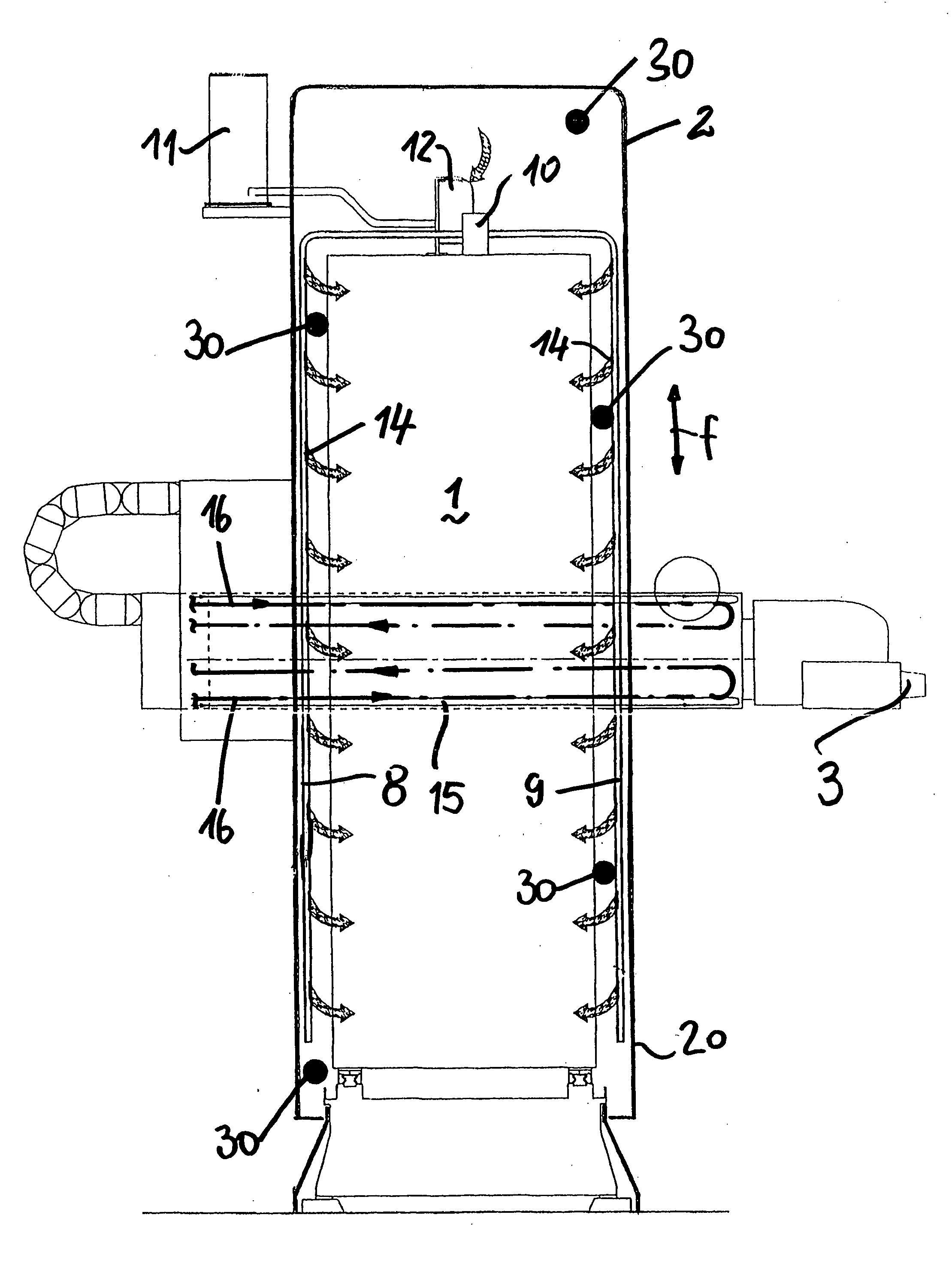
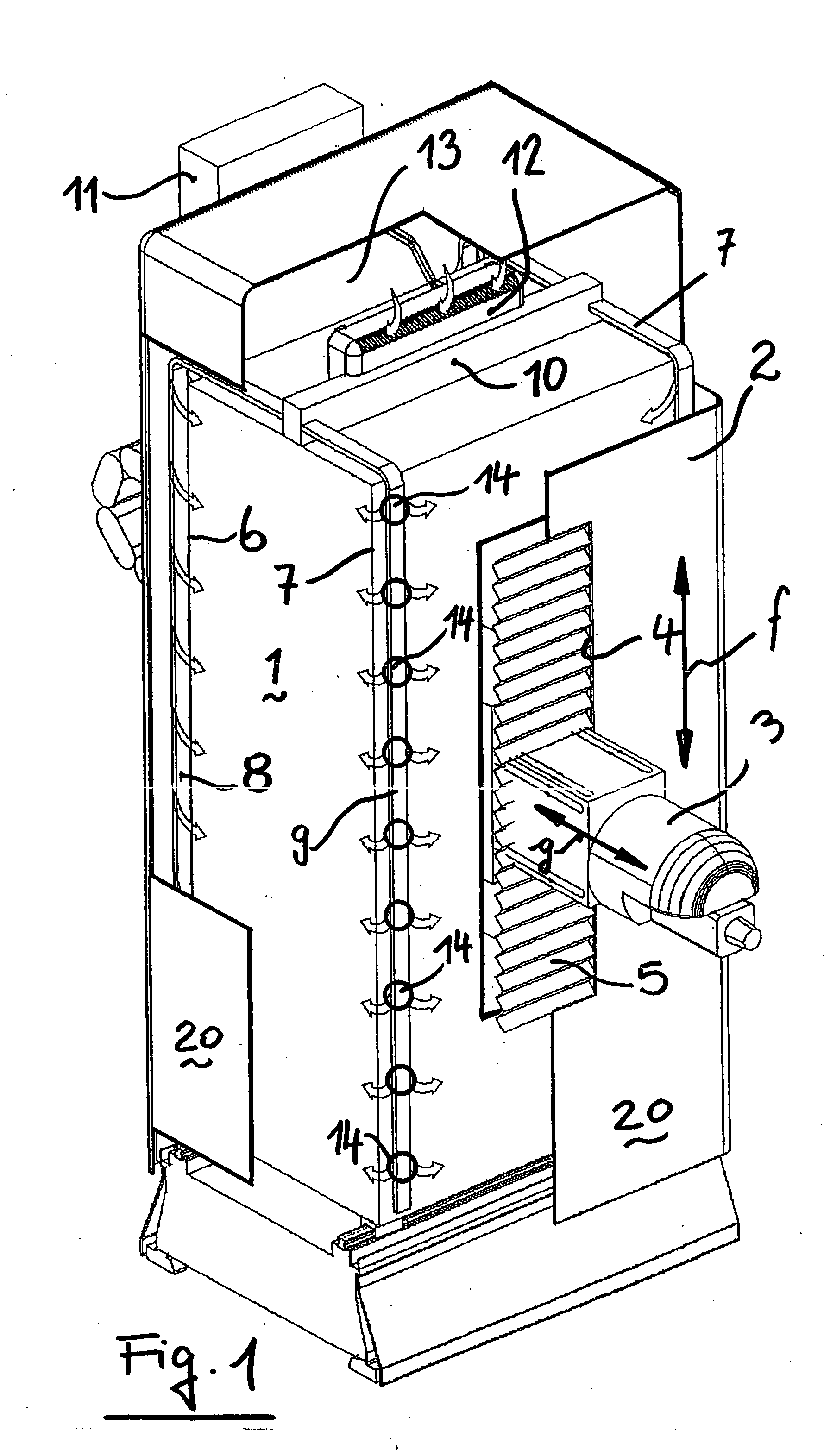
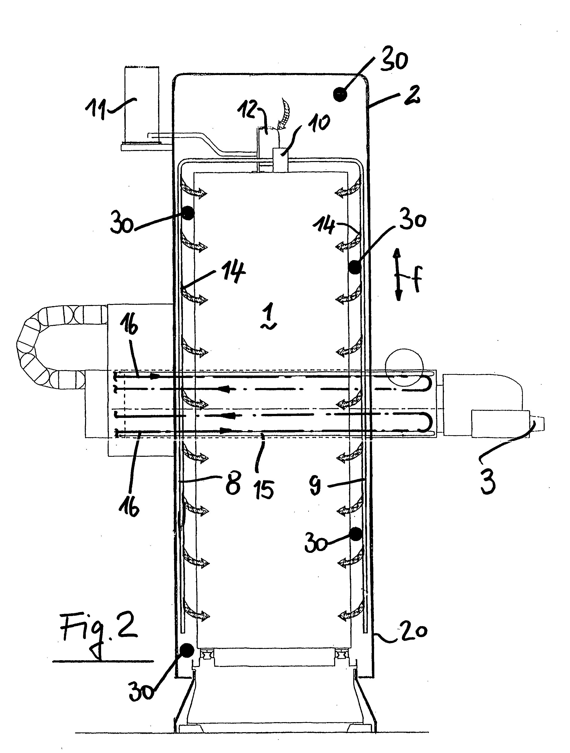
[0015] As shown in FIG. 1, the machine tool, generally indicated herein by the reference number 1, for example a milling machine, is arranged inside a casing 2, made of a thermally insulating material and fixed to a machine tool framework.

[0016] The overall construction or framework of the machine tool 1, in particular, is housed in the casing. A spindle bearing head 3 extends out from the casing.

[0017] Since the spindle bearing head 3 of a boring or milling machine can be driven in the direction indicated by the double-headed arrows f, g, the casing 2 comprises an opening 4, including a sealing bellows 5.

[0018] Moreover, near the corners 6, 7 or other not shown corner parts, and other regions of the machine tool framework 1, a plurality of ducts 8 and 9 extending along the overall height of the machine tool are provided. The ducts 8 and 9, and other pipes, lead to one or more manifolds 10, which have been indicated only schematically. The manifold 10 is operatively connected to ...


PUM

PropertyMeasurementUnit
thermally insulatingaaaaaaaaaa
temperaturesaaaaaaaaaa
temperatureaaaaaaaaaa

Abstract

In a conditioning system for a manufacturing machine, in particular a machine tool, a machine tool framework is arranged inside a sealed casing. Ducts are arranged at machine tool regions to be thermally conditioned. The ducts comprise air flow outlets and are coupled to a conditioned air delivery manifold supplied by a conditioning device. Solenoid valves are provided at the outlets to control air flow.

Description

BACKGROUND OF THE INVENTION [0001] 1. Field of the Invention [0002] The present invention generally relates to a thermal conditioning system for a manufacturing machine, in particular, a machine tool. [0003] 2. Description of the Related Art [0004] As is known, prior manufacturing machines, particularly machine tools, comprise a plurality of driving motors so designed as to allow movable parts of the machine to be accurately driven. [0005] However, both temperature variations occurring at the site of the machine tool, and heat from the machine tool driving motors, as well as friction heat generated as movable parts of the machine tool are driven, cause an undesired uneven heating of the machine tool main body, and of the movable parts thereof. [0006] To overcome, at least partially, the effects due to the abovementioned uneven heating of the machine tool, which would decrease the required machining accuracy, it has been already suggested to provide, in prior art machine tools, chann...

Claims


Application Information

Patent Timeline
Patent Type & Authority Applications(United States)
IPC IPC(8): B23Q11/12B23Q11/14B60H1/00
CPCB23Q11/128Y10T409/303976B60H1/00B23Q11/148
Inventor PARPAJOLA, VLADI
Owner PARPAS
Learn More