
Heating and cooling system

a technology for heating and cooling systems and vehicles, applied in the direction of machine operation, lightening and heating apparatus, transportation and packaging, etc., can solve the problems of overpowering operation, large size of current available systems, and high cost of purchase and operation, and achieve compact size, adequate heating and cooling capacity, and the effect of improving efficiency

Active Publication Date: 2005-04-14
PARKS IND LLC
View PDF8 Cites 6 Cited by
  • Summary
  • Abstract
  • Description
  • Claims
  • Application Information

AI Technical Summary

Benefits of technology

"This patent describes a heating and cooling system for vehicles that is compact, efficient, and cost-effective. The system has a heat pump that can cool or heat the vehicle, depending on the needs. It can provide power for small appliances and also maintain the vehicle's battery charge. The system is designed to improve fuel economy and reduce air pollution. The technical effects of this invention include improved efficiency, reduced costs, and improved performance of vehicles in extreme weather conditions."

Problems solved by technology

The currently available systems are generally too large, too heavy, overpowering in operation, and expensive to purchase and to operate.
The units weigh approximately 450 lb to 500 lb, which consumes more fuel just to carry that weight when the vehicle moves.
These sizable components occupy significant space proximate to a vehicle or truck cab.
The prior art systems are significantly large, heavy, and overpowered in cooling or heating capacity, for the cab in which they are employed.

Method used


Image

  • Heating and cooling system
  • Heating and cooling system
  • Heating and cooling system

Examples


Embodiment Construction

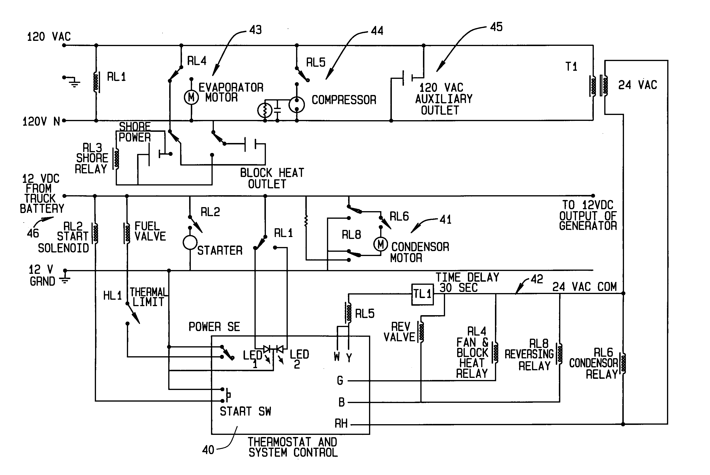
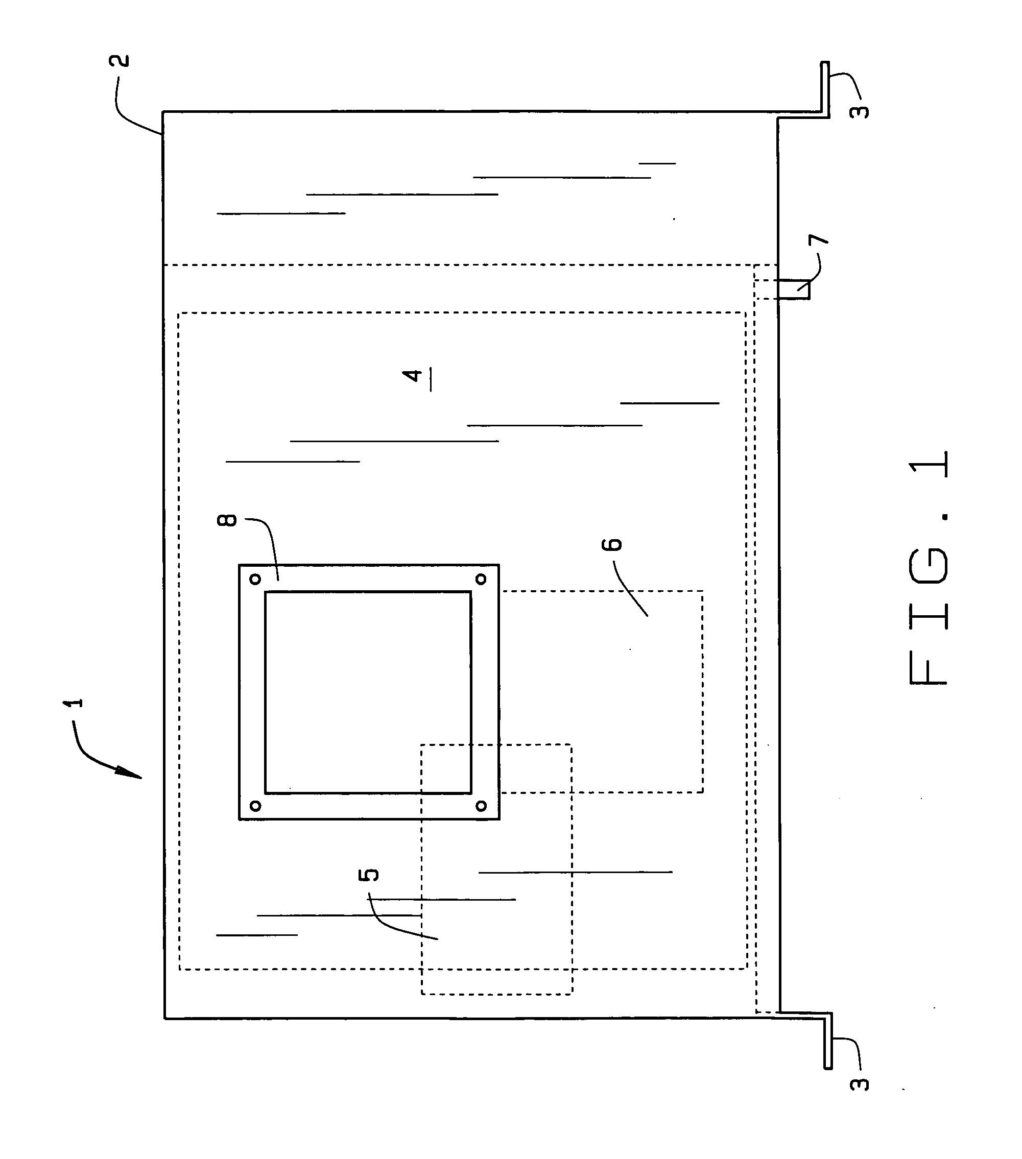
[0029] In referring to the drawings, and in particular FIG. 1, the heating / cooling system of this invention is shown at 1. The evaporator unit is encased within a housing 2, and has base angles, as at 3, at each corner of the housing, to provide for securement by fasteners of the unit to a stable framework. As the evaporator unit for the system it includes an evaporator coil 4, a motor 5, and a blower 6, that is operated by the motor. Normally the blower has a capacity of approximately 275 cubic feet per minute depending upon the needs of the system and its location. An evaporator drain 7 is located at the housing's 2 bottom to discharge any water collected. An access door 8 allows for servicing. Venting is provided through the housing 2 to a vehicle cab, or confined space, at locations convenient for installation as well as door 8.

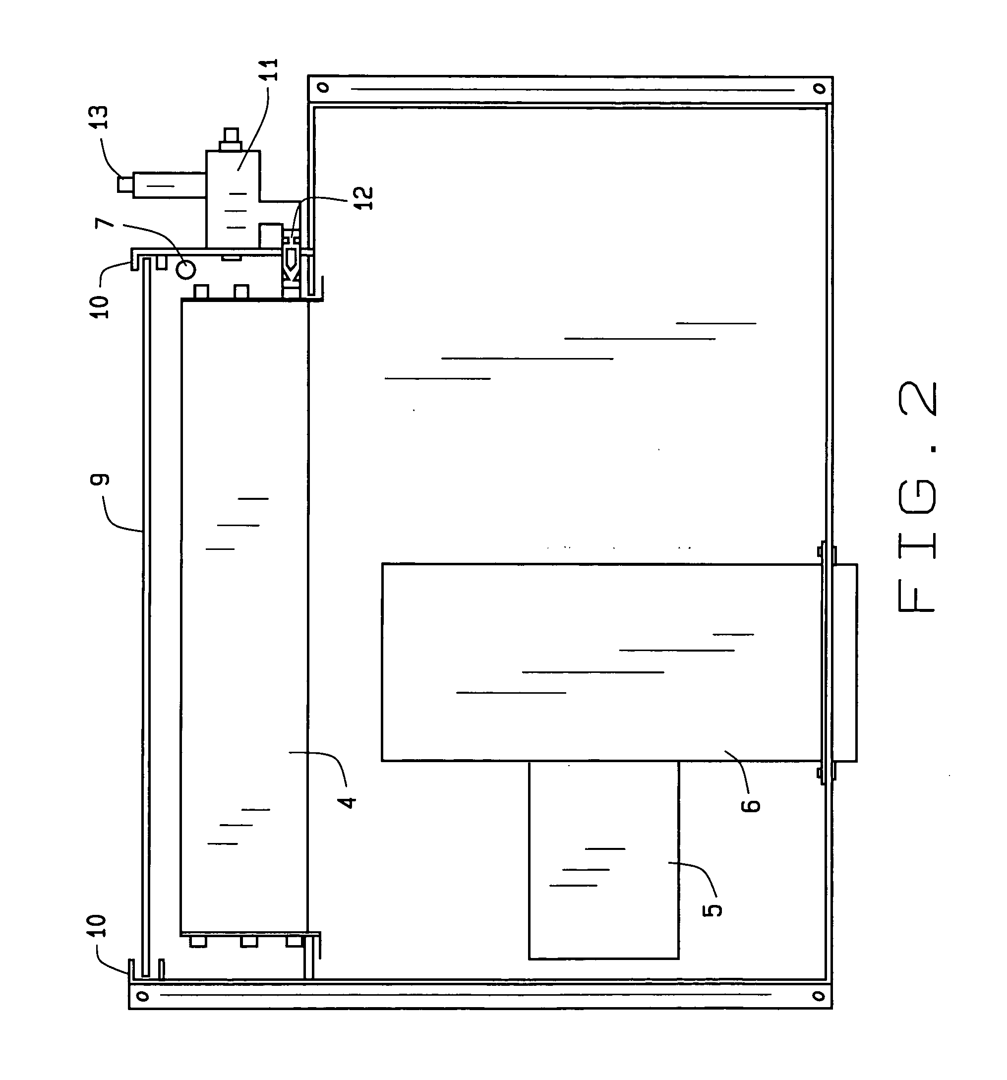
[0030]FIG. 2 provides a top plan view of the evaporator unit of FIG. 1. As can be seen, the evaporator motor 5 operates on approximately 115 volt servic...


PUM


Abstract

A heating and cooling system incorporates a heat pump that operates conventionally with air drawn from outside the system through its condenser coils that remove heat to the exterior for cooling. In the heating cycle, the condenser motor blower stops and reverses rotation. Outside air is drawn in by the condenser fan, is circulated across the diesel engine and generator, and is blown through the condenser coils outside of the unit. In the heating cycle, a circuit monitors the temperature of the compressor coil and controls the speed of the condenser motor. The heat recovery method of the system maintains power input to heat output ratios in excess of 2:1, even at low outside temperatures. The recovery method also allows the system to operate without defrost cycles. This system may provide auxiliary power, block heat, and battery charging, utilizing a small diesel engine and generator components, and can be installed within a truck, bus, boat, cabin, camper, and the like.

Description

CROSS REFERENCE TO RELATED APPLICATION [0001] This patent application claims priority from a provisional application having Ser. No. 60 / 505,722 and filed on Sep. 25, 2003.BACKGROUND OF THE INVENTION [0002] This invention relates generally to heating and cooling systems for vehicles and specifically to systems which operate from an auxiliary power generator system. The present invention provides DC power for battery charging, controls the vehicle environment for the truck, camper, van, or bus driver and boater while he operates the vehicle and during down time, all the while in compliance with the anti-idling laws. [0003] Various heating and cooling systems and their generator are currently manufactured for tractor trailers. Other vehicles, such as buses, boats, houseboats, camping trailers, and the like, also have heating and cooling systems, and auxiliary components. The currently available systems are generally too large, too heavy, overpowering in operation, and expensive to purc...

Claims


Application Information

Patent Timeline
Patent Type & Authority Applications(United States)
IPC IPC(8): B60H1/32F25B13/00F25B27/00
CPCB60H1/3226F25B13/00F25B27/00F25B2500/31F25B2313/0294F25B2500/01F25B2313/0293
Inventor PARKS, GARY L.ROSSIN, GARY W.
Owner PARKS IND LLC
Learn More