Multi-piece machine tool base

a multi-piece machine tool and base technology, applied in the direction of manufacturing tools, rotary cutting tools, flat surfacing machines, etc., can solve the problems of largely inadequate portable planing machines

Inactive Publication Date: 2005-04-14
WIXEY BARRY +3
View PDF29 Cites 8 Cited by
  • Summary
  • Abstract
  • Description
  • Claims
  • Application Information

AI Technical Summary

Problems solved by technology

While such designs have proven to be acceptable for relatively large planing machines which are repositioned on...

Method used


Image

  • Multi-piece machine tool base
  • Multi-piece machine tool base
  • Multi-piece machine tool base

Examples


Embodiment Construction

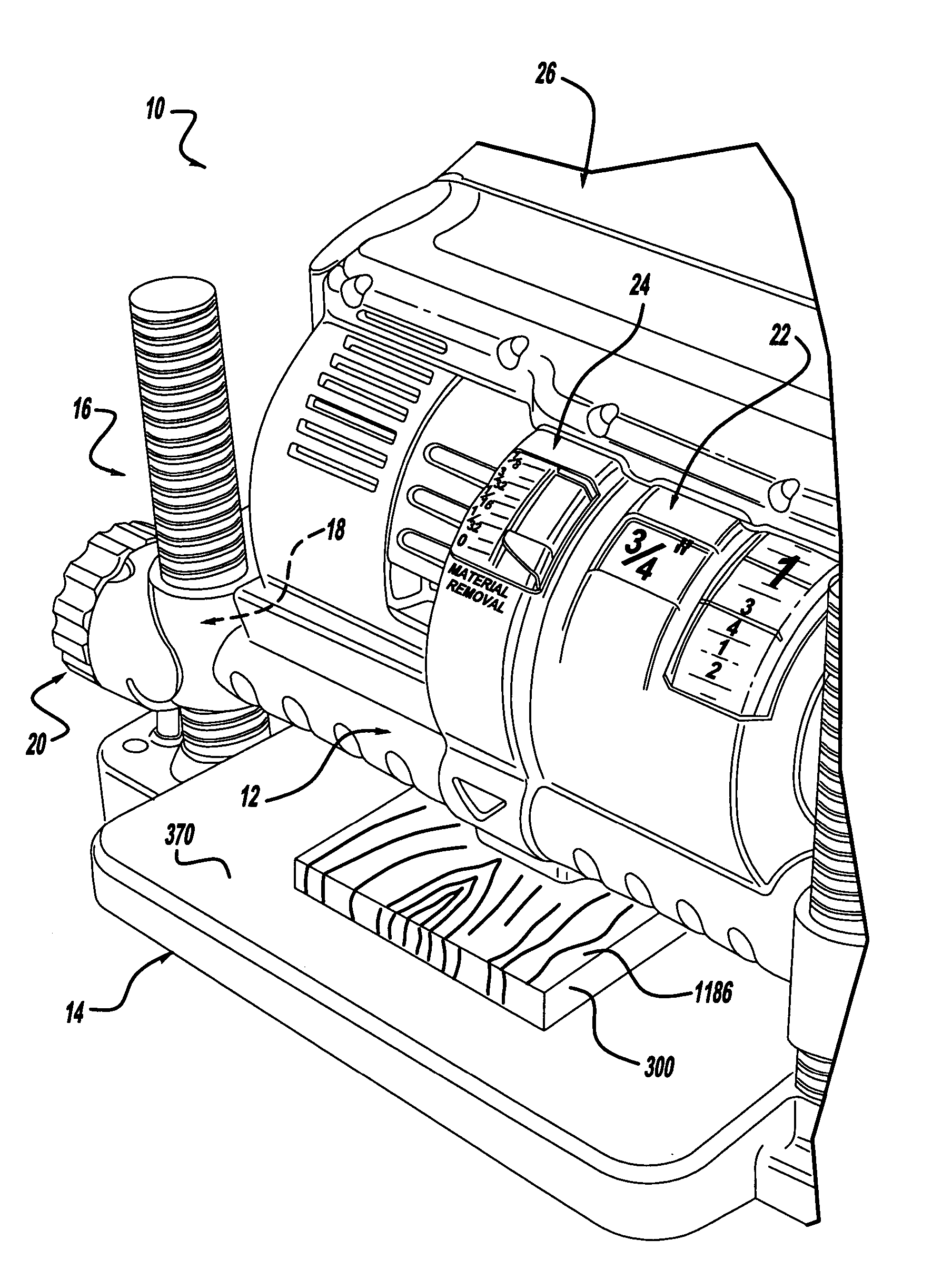
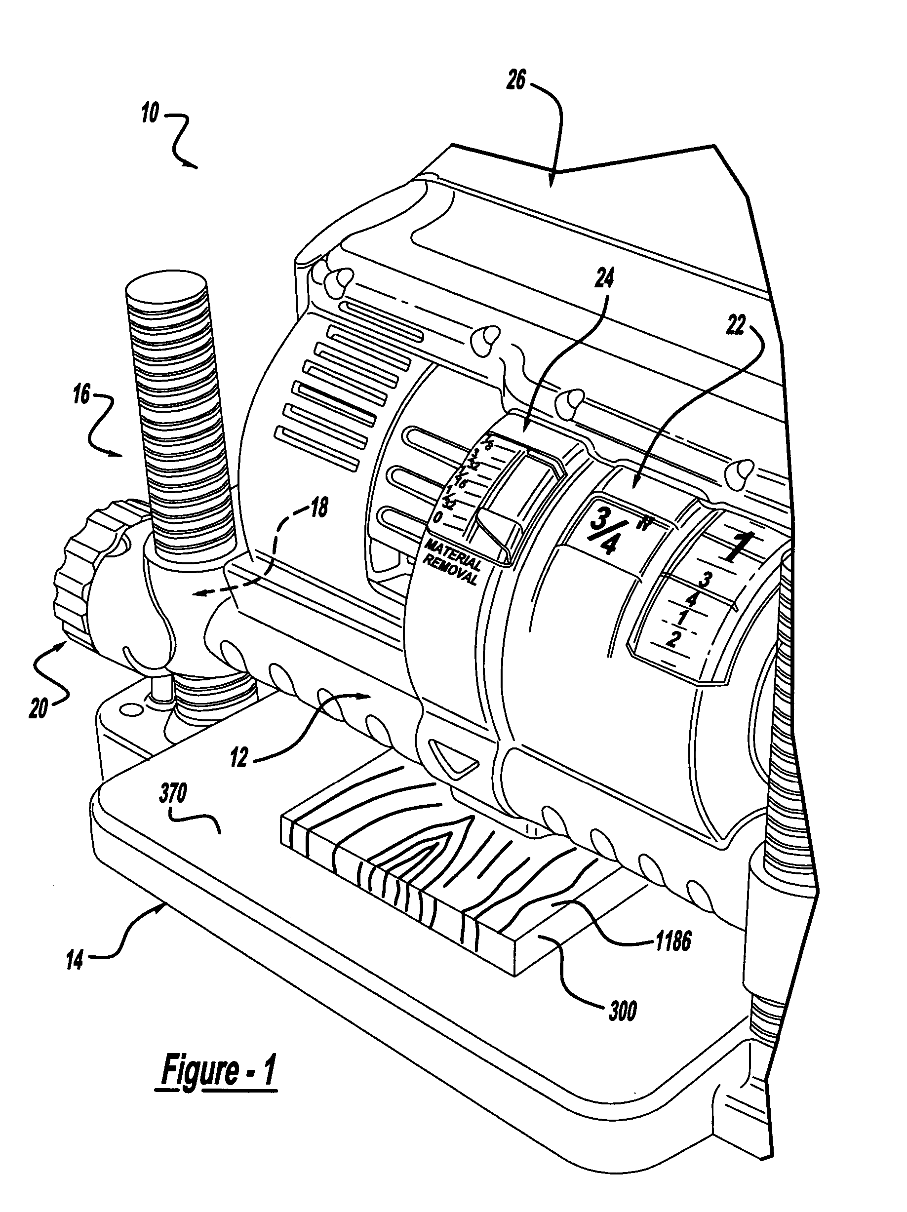
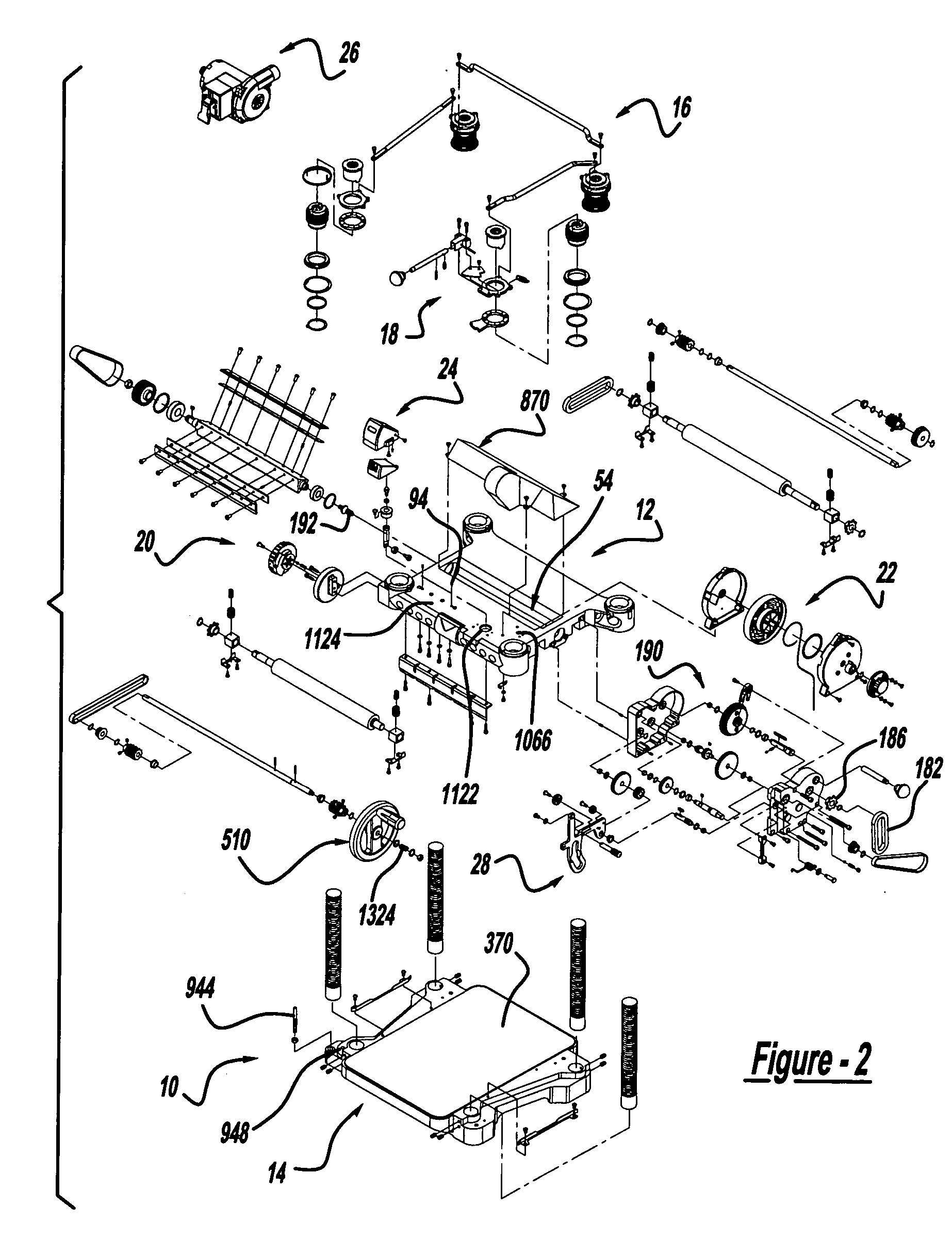
[0057] With reference to FIG. 1 of the drawings, a planer mechanism constructed in accordance with the teachings of the present invention is generally indicated by reference numeral 10. With additional reference to FIG. 2, the planer mechanism 10 is shown to include a planer carriage assembly 12, a base assembly 14, a planer carriage elevation mechanism 16, a planer carriage locking mechanism 18, a carriage height setting mechanism 20, a height scale mechanism 22, a material removal gauge 24, a dust collection system 26 and a power take-off mechanism 28.

[0058] Planer Carriage Assembly

[0059] In FIG. 3, the planer carriage assembly 12 is illustrated to include a carriage 40, a motor assembly 42, a gearbox 44, a first roller assembly 46, a second roller assembly 48 and a cutterhead assembly 50, which will be discussed in more detail below. The carriage 40 is a unitarily formed structure having a cutter pocket 54, two pair of square apertures 58 and a plurality of nut apertures 60, wh...


PUM

PropertyMeasurementUnit
Structureaaaaaaaaaa

Abstract

A power tool having a base assembly with a first portion, which defines an upper surface, and a second portion that defines a lower surface. The first and second portions may be castings and are coupled to one another without machining the upper surface of the first portion or the lower surface of the second portion. After assembly of the base portion, the upper surface of the second portion is machined to define a flat reference surface. Construction of the power tool in this manner provides a robust base assembly that is relatively inexpensive to manufacture. A related method is also provided.

Description

CROSS-REFERENCE TO RELATED APPLICATIONS [0001] This application is a divisional application of U.S. patent application Ser. No. 10 / 731,792 filed Dec. 9, 2003, which is a divisional application of U.S. patent application Ser. No. 10 / 124,746 filed Apr. 17, 2002 (now U.S. Pat. No. 6,601,621 issued Aug. 5, 2003), which claims priority to U.S. Provisional Application Ser. No. 60 / 284,486 filed on Apr. 18, 2001, entitled “Portable Power Planer”.FIELD OF THE INVENTION [0002] The present invention generally relates improvements in portable power tools, and more specifically to improvements that are particularly well suited for use with wood working power tools such as portable power planers. BACKGROUND OF THE INVENTION [0003] Various power tools are used in woodworking in an effort to efficiently and accurately form workpieces to desired dimensions and with a desired surface finish. As is widely known, planing machines are often used for surface planing of wooden boards. A conventional plani...

Claims


Application Information

Patent Timeline
IPC IPC(8): B23Q11/00B23Q17/22B27C1/04B27C1/14B27G13/04
CPCB23Q11/0046B23Q17/22B27C1/04B27C1/12Y10T409/304088B27G13/04Y10T409/308176Y10T409/308624Y10T403/7071B27C1/14
Inventor WIXEY, BARRYWELSH, ROBERT P.WIKLE, DAVID L.DOSS, DAVID J.
Owner WIXEY BARRY
Why Eureka
Try Eureka