Method and apparatus for continuous separation and reaction using supercritical fluid

a supercritical fluid and continuous separation technology, applied in the direction of solid separation, hydrocarbon oil refining, chemical/physical processes, etc., can solve the problems of further remediation, complex process of treating used oils, and high cost and time consumption, so as to reduce or eliminate another cost element, minimize waste components, and minimize the production of rag layers

Active Publication Date: 2005-04-14
SMART TIRE RECYCLING INC
View PDF24 Cites 6 Cited by
  • Summary
  • Abstract
  • Description
  • Claims
  • Application Information

AI Technical Summary

Benefits of technology

[0017] Another aspect of the present invention is that it minimizes waste components that require further remediation. For example, when the present invention is used to process a petroleum product, the amount of water and other residues in the starting material does not alter the quality of the final product or its fundamental process procedure. The present invention minimizes the production of the rag layer, that is, un-dissolved oil residue and water layer. This reduces or eliminates another cost element, that is, disposing of the rag layer. The separated components (still under high pressure) can be made harmless to the environment by additional reactions, such as breaking down PCB's into harmless chemicals using on line supercritical water oxidation.
[0018] Another aspect of the present invention is that this system can be easily scaled or adapted to both volume and flow. Energy is conserved in the process as part of the fundamental design. The present invention can be scaled down to be dedicated for some specific applications. For example, it can be used on a small scale to recycle well-defined used oil, such as on merchant or navy ships, military engines and other such applications. The clean product can be used as clean engine oil after making up some of the depleted additives.
[0019] The present invention is also so compact that it can be used as a mobile processing system making it possible to take the present invention to the source. This is a strategic advantage and one that may introduce a new paradigm in this field. Because of this compact nature it is also possible to integrate the purification into other mechanical systems to continuously purify oil and solvent components.
[0020] The fundamental nature of the present invention is more amenable to real time application in conjunction with other process. The continuous operation and the fewer requirements for a holding tank, allow the process to be applied in other than tank or tanker batches and permit a new flexibility. By adding one module to the existing system it can also be used as a dedicated application for cleaning of oil contaminated solids such as metal parts, machinery or rags with the oil directed to the oil purification process.

Problems solved by technology

Currently, on-site remediation of these waste streams proves to be quite costly.
This process of treating used oils is complex, costly and time consuming and produces waste components that require further remediation.
Further, these used oils that are burned as fuel oils result in the original value of the oil being greatly reduced.
It has been the lack of an economical purification process of sufficient quality that has prevented the direct reuse or higher value use of these materials.
Both are fundamentally limited due to the specific technology and design approach.
Batch systems operate at very high pressure and employ vessels of large volume; these systems are extremely expensive and inefficient.
Systems of this type are very inefficient and rely on a large surface area on a wire mesh inside the column to strip off lighter components from the feed liquid.
It requires many temperature sensors and complex controls, and it has very limited flow efficiency.
The process is not very efficient economically due to the relatively low solubility of lubricant in carbon dioxide.
The batch process lowers the competitiveness of the process.

Method used


Image

  • Method and apparatus for continuous separation and reaction using supercritical fluid
  • Method and apparatus for continuous separation and reaction using supercritical fluid
  • Method and apparatus for continuous separation and reaction using supercritical fluid

Examples


Embodiment Construction

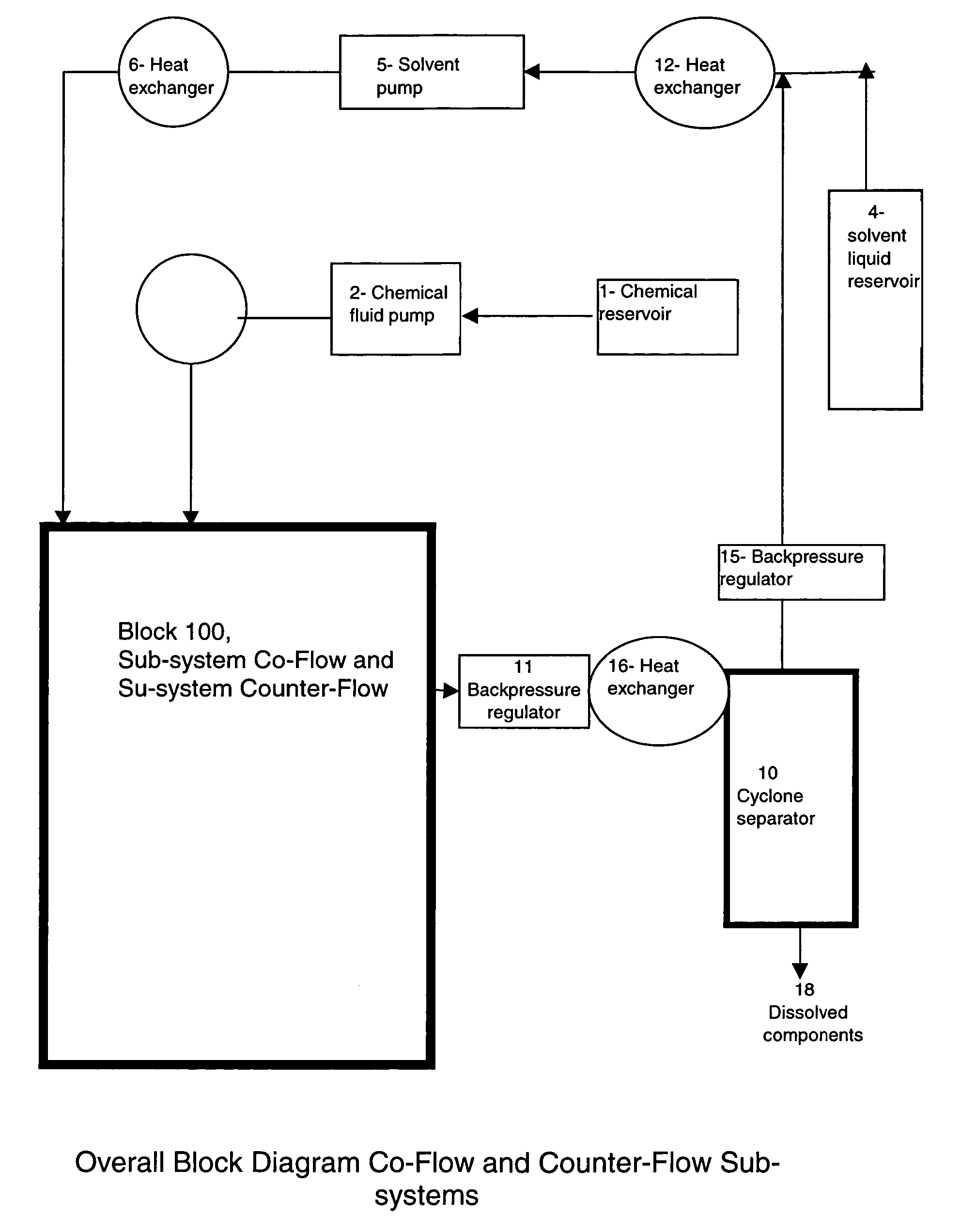
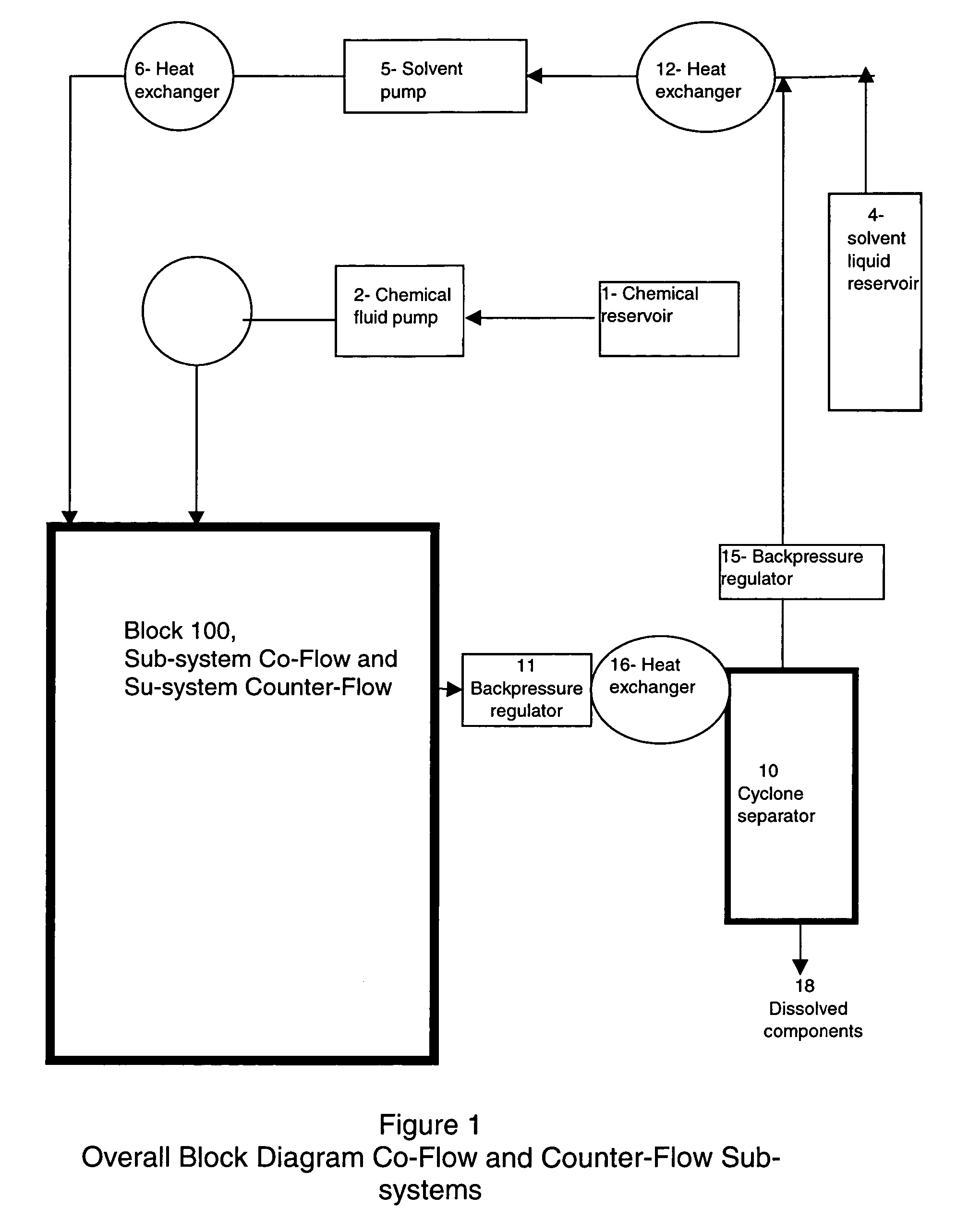
[0022]FIG. 1 depicts a block diagram of the major elements of a system capable of practicing the method of the present invention. The fluid to be processed is transferred from the chemical reservoir (1) by chemical fluid pump (2) into a heat exchanger (3), then into the sub-system (100). The sub-system (100) may be either co-flow or counter-flow, and the operation of each is discussed in detail below. Supercritical fluid is transferred from solvent liquid reservoir (4) by solvent pump (5) into high-pressure heat exchanger (6) to achieve supercritical conditions of temperature and pressure, then the supercritical fluid enters reactor (100). The high-pressure reactor is maid of metal alloy, which is not compatible with using another form of heating such as microwave. In addition using microwave compatible material such as peek will limit the maximum pressure and reduce the efficiency and the safety of the process. The dissolved components in the supercritical fluid are phased out from...


PUM

PropertyMeasurementUnit
angleaaaaaaaaaa
pressureaaaaaaaaaa
pressureaaaaaaaaaa

Abstract

A method for the continuous process of fluids is based on mixing the fluid with a supercritical fluid. The mixing of the two fluids may be accomplished using either a co-flow or counter-flow process. The process focuses on the difference in the solubilities of the desired and the undesired components into supercritical fluid and de-emphasizes the influence of the contaminating components of the fluid to be processed. The process of the present invention is particularly advantageous to the recycling of industrial waste fluids, such as used oil, wherein the process is carried out by jet spray micro-orifices atomization of waste material with a supercritical fluid to dissolve oil from the waste material. Additional mixing devices such as a magneto driven impeller shaft and ultrasonic gun may be employed. Thereafter, un-dissolved components are separated, first and the dissolved fluid is then separated from the supercritical fluid. Various apparatus for carrying out the method are also disclosed.

Description

FIELD OF THE INVENTION [0001] The present invention generally relates to continuous separation and reaction of chemical fluids (liquids, solutions and gases) using supercritical fluids, and more particularly to the separation of industrial fluids into sub-components based on the different solubility of the components in supercritical fluids. BACKGROUND OF THE INVENTION [0002] There are a number of applications in which chemical components in a mixture need to be separated. The fields of application include many industries such as chemical, environmental, food, medical, enzymatic, pharmaceutical and recycling. The problems to be overcome by the present invention will now be discussed with reference to the recycling industry, but it should be understood this discussion is representative of the problems faced by the other industries. [0003] Used lubricating and hydraulic oils are generated by a number of industries, including automotive and commercial shops, large industrial manufactur...

Claims


Application Information

Patent Timeline
Patent Type & Authority Applications(United States)
IPC IPC(8): C10G21/00C10M175/00
CPCC10M175/00C10G21/00
Inventor ALKHALIDL, ABDULHAQ E.
Owner SMART TIRE RECYCLING INC
Why Eureka
Try Eureka