Heat pipe

Inactive Publication Date: 2005-04-14
MCGILL UNIV
View PDF7 Cites 10 Cited by
  • Summary
  • Abstract
  • Description
  • Claims
  • Application Information

AI Technical Summary

Benefits of technology

[0022] Therefore, in accordance with the present invention, there is provided a heat pipe assembly, under vacuum and having a working substance charged therein, comprising: an evaporator adapted to evaporate the working substance and having a closed leading end; a heat exchanging condenser being in fluid flow communication with the evaporator, the condenser being adapted to condense vaporized working substance received from the evaporator and having a reservoir located at a higher elevation than the evaporator for collecting liquid working substance therein; a discrete, impermeable liquid return passage permitting the flow, by gravity, of the liquid working substance from the reservoir to the evaporator; the liquid return passage extending through the evaporator and terminating near the closed leading end thereof; and a flow modifier positioned within the evaporator section, causing swirling working substance flow in the evaporator; whereby the flow modifier ensures that un-vaporized liquid entrained with evaporated working substance is propelled against inner surfaces of the evaporator by centrifugal force to ensure liquid coverage of the inner surfaces, thereby delaying onset of film boiling.

Problems solved by technology

Conversely, if the heat pipe chamber develops a leak, the heat pipe will cease to function.
Thus, the use of a heat pipe in a high temperature environment can be problematic if the evaporator experiences insufficient cooling as this can cause the containment vessel to be perforated with the subsequent failure of the heat pipe.
While both loop and non-loop (i.e. countercurrent) heat pipes have been used in a number of products and applications, they have not been incorporated in units where high heat fluxes at high operating temperatures are encountered and they are generally not used in large scale units.
This is largely because such systems are amenable to failure of the containment material that forms the heat pipe.
This has not been possible as yet with the heat pipes of the prior art.
Thus, insufficient cooling of even a relatively small region (e.g. 10 mm2) can lead to the perforation and subsequent destruction of the heat pipe unit.
Heat pipes of the prior art have rarely been intended for use in applications involving high operating temperatures, and as such, destruction of a heat pipe chamber as a result of exposure to elevated temperatures has never been adequately addressed.
However, this heat pipe nevertheless fails to overcome the principle difficulties associated with all countercurrent heat pipes used in high heat flux applications.
The three main limitations of prior art heat pipes that must be overcome to make their use in high temperature applications feasible are: film boiling on the evaporator walls, levitation of the liquid returning to the evaporator, and configurational complexity of a loop heat pipe for certain applications.
The levitation of liquid from the leading end of the evaporator will reduce heat transfer efficiency and will, if the temperatures are high enough, cause the heat pipe to fail as a result of dry-out.
The other principle difficulty with using heat pipes in high heat flux applications is the onset of film boiling on the evaporator walls.
This dramatically reduces the heat transfer efficiency and, in some cases, may lead to the destruction of the evaporator containment walls.
However, the heat pipe lance of U.S. Pat. No. 5,310,966 fails to teach how to eliminate the levitation of liquid from the leading end of the evaporator or how to eliminate the formation of a stable vapor film on the inner walls of the evaporator.
Loop heat pipes can overcome the issue of entrainment, however, loop heat pipes are often not viable for many practical applications because of their configurational complexity, wherein the return loop pipe is run outside the main heat pipe body which significantly increases space requirements of the heat pipe.
Nevertheless, as with countercurrent heat pipes, the problem of film boiling on the evaporator surfaces nevertheless remains.
The mechanism for evaporation remains an important limiting factor in a heat pipe, and especially for high heat flux applications.
The evaporator has then attained its boiling limit, and the subsequent result of continued exposure to the heat flux can be overheating of the evaporator walls and possible failure of the heat pipe.

Method used


Image

  • Heat pipe
  • Heat pipe
  • Heat pipe

Examples


Embodiment Construction

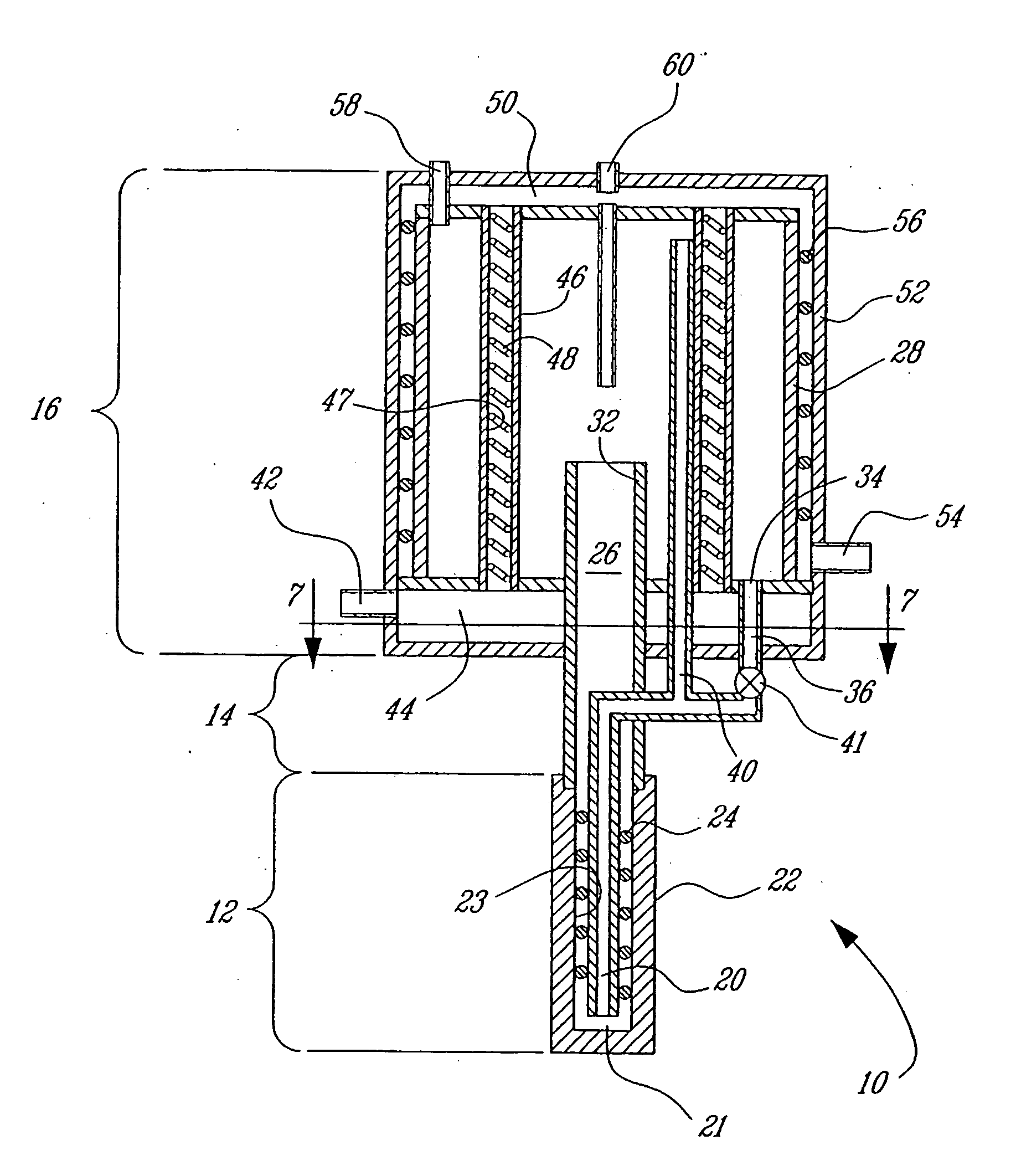
[0035] The heat pipe of the present invention is comprised principally of an evaporator, a coupling element, and a condenser, and comprises generally two principle embodiments, whose main classes of applications are as an energy extractor as shown in FIG. 5, and as a injection unit as shown in FIG. 6. In the latter, the heat pipe has one or more conduits that run through the unit to carry reagents. Examples of the use of such a heat pipe would be injection lances, tuyeres and burners. In the former class of applications, the heat pipe has no reagent-carrying conduit in the heat pipe, and is used for transferring energy, for example as a heat extraction device. The two embodiments are thus differentiated by whether or not a reagent is transported through the heat pipe unit.

[0036] Referring to FIG. 5 showing the first embodiment of the invention, the energy extraction heat pipe unit 10 comprises generally an evaporator 12, a coupling element 14, and a condenser 16.

[0037] The evapora...


PUM

PropertyMeasurementUnit
Temperatureaaaaaaaaaa
Flow rateaaaaaaaaaa
Flexibilityaaaaaaaaaa

Abstract

A heat pipe assembly (10 / 110), under vacuum and having a working substance charged therein, comprising generally an evaporator (12 / 112) adapted to evaporate the working fluid and a condenser (16 / 116). The heat exchanging condenser is in fluid flow communication with the evaporator. The condenser is adapted to condense evaporated working substance received from the evaporator and has a reservoir (30 / 130), located at a higher elevation than the evaporator, for collecting liquid working fluid therein. A discrete, impermeable liquid return passage (36 / 136, 20 / 120) permitting the flow, by gravity, of the liquid working substance from the reservoir to the evaporator. The liquid return passage extends through the evaporator and terminates near the closed leading end thereof, and is fitted with a vent line (38 / 138) that diverts ascending vapor to the top of the condenser. A flow modifier (24 / 124) is positioned within the evaporator, causing swirling working fluid flow in the evaporator, whereby the flow modifier ensures that un-vaporized liquid entrained with evaporated working substance is propelled against inner surfaces (23 / 123) of the evaporator by centrifugal force to ensure liquid coverage of the inner surfaces, thereby delaying onset of film boiling.

Description

RELATED APPLICATIONS [0001] This is a continuation of International Patent Application No. PCT / CA02 / 01394 filed Sep. 13, 2002, which claims benefit of U.S. Provisional Patent Application No. 60 / 358,724 filed on Feb. 25, 2002.BACKGROUND OF THE INVENTION [0002] 1. Field of the Invention [0003] The present invention relates generally to a heat pipe, and more specifically to a semi-loop heat pipe having co-current, swirling two phase flow in the evaporator, and an impermeable return line from the condenser. [0004] 2. Description of the Prior Art [0005] Heat pipes are devices that employ the evaporation and condensation of a working fluid contained within to effect the transfer of energy from the evaporator where heat is absorbed to the condenser where the heat is released. Heat pipes gained prominence in the early 1960's as superconducting, heat transfer devices as detailed, for example, in U.S. Pat. Nos. 3,229,759 and 4,485,670. While numerous configurations and applications of heat pi...

Claims


Application Information

Patent Timeline
IPC IPC(8): F28D15/02F28D15/04F28D15/06F28F13/06
CPCF28D15/0266F28F13/06F28D15/06F28D15/043F28D15/02F28D15/04
Inventor MUCCIARDI, FRANKGRUZLESKI, JOHNZHENG, GUOHUIZHANG, CHUNHUIYUAN, ZHONGSEN
Owner MCGILL UNIV
Why Eureka
Try Eureka