Emitter for electron-beam projection lithography system, and method of manufacturing and operating the emitter

a technology of electron beam and projection lithography, which is applied in the manufacture of electrode systems, electric discharge tubes/lamps, nuclear engineering, etc., can solve the problems of system limitation in how narrow a line width they can realize, and cannot permit such partial election emission

Inactive Publication Date: 2005-04-14
SAMSUNG ELECTRONICS CO LTD
View PDF5 Cites 4 Cited by
  • Summary
  • Abstract
  • Description
  • Claims
  • Application Information

AI Technical Summary

Benefits of technology

[0009] The present invention is therefore directed to an electron-beam emitter, method of making the electron-beam emitter, and method of usi...

Problems solved by technology

Optical lithography systems using visible light have been widely employed, but these systems are limited in how narrow ...

Method used


Image

  • Emitter for electron-beam projection lithography system, and method of manufacturing and operating the emitter
  • Emitter for electron-beam projection lithography system, and method of manufacturing and operating the emitter
  • Emitter for electron-beam projection lithography system, and method of manufacturing and operating the emitter

Examples


Embodiment Construction

[0026] Korean Patent Application No. 2003-70990, filed on Oct. 13, 2003, in the Korean Intellectual Property Office, and entitled: “Emitter for Electron-beam Projection Lithography, operating method and manufacturing Method thereof,” is incorporated by reference herein in its entirety.

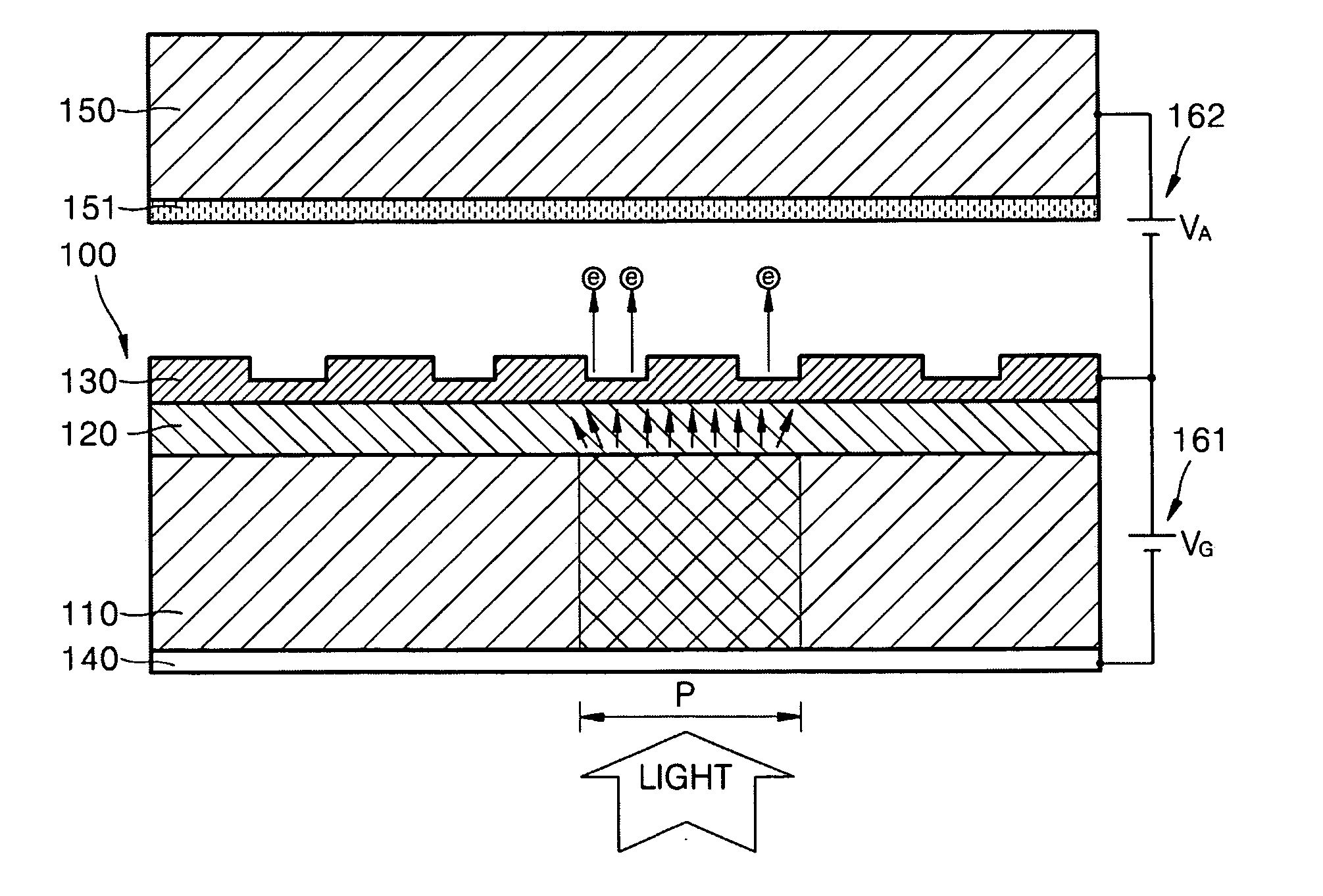
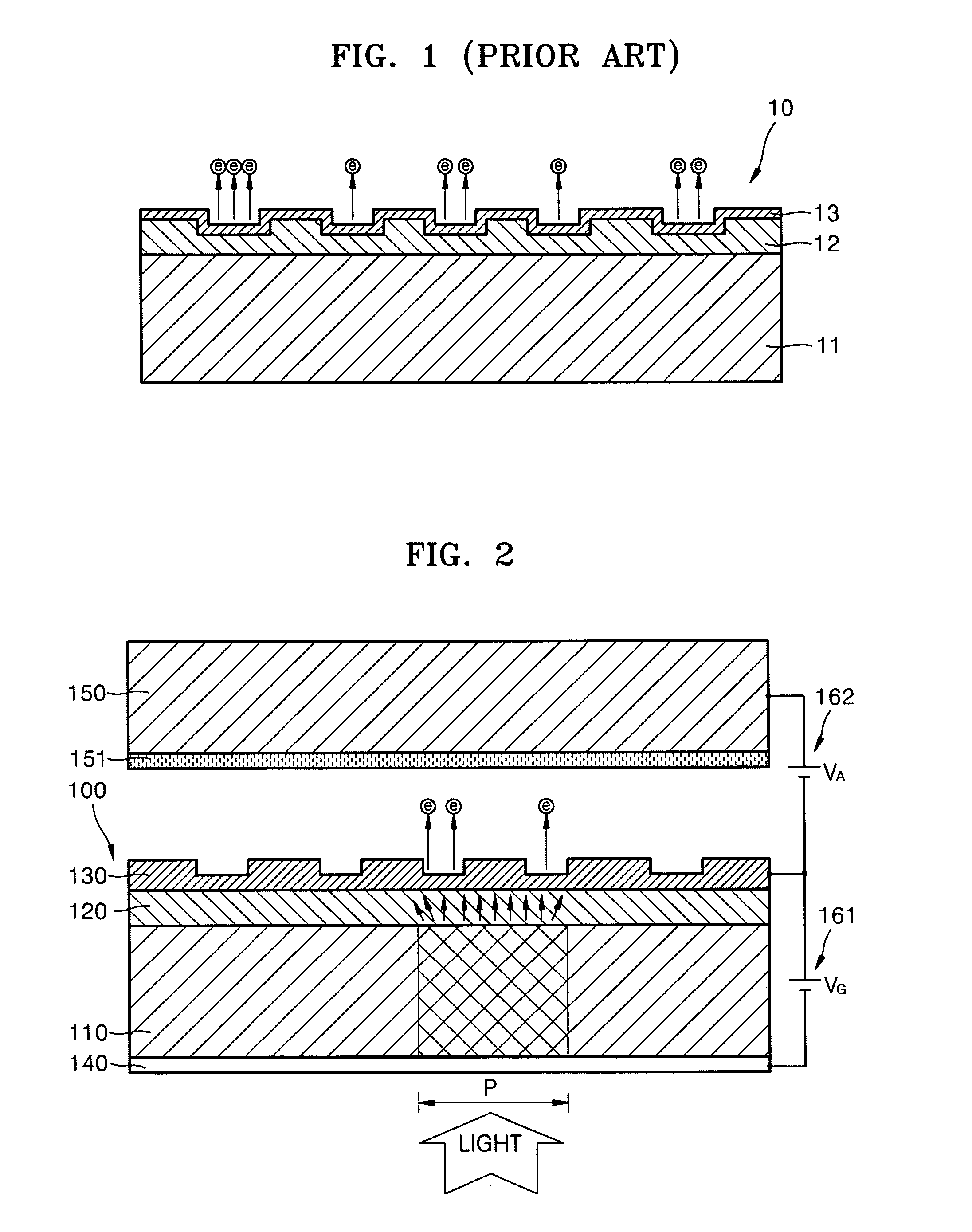
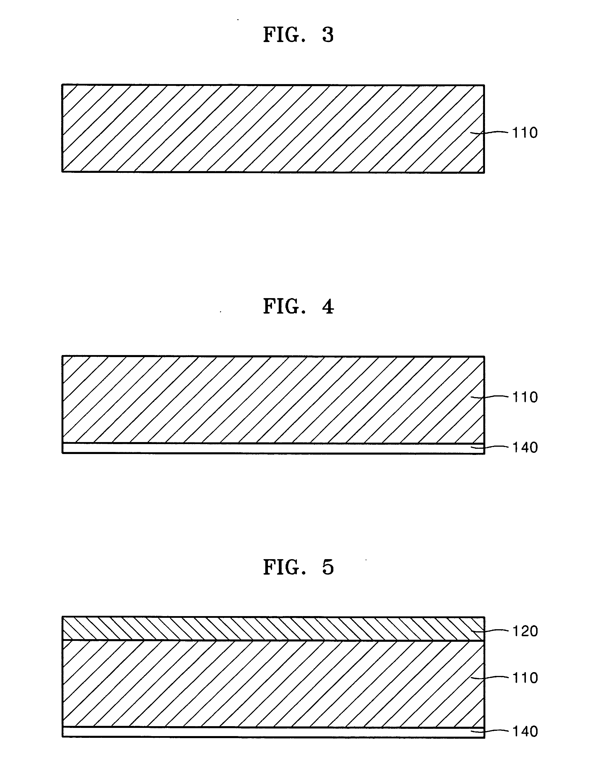
[0027] The present invention will now be described more fully with reference to the accompanying drawings, in which exemplary embodiments of the invention are shown. The invention may, however, be embodied in different forms and should not be construed as limited to the embodiments set forth herein. Rather, these embodiments are provided so that this disclosure will be thorough and complete, and will fully convey the scope of the invention to those skilled in the art. In the figures, the dimensions of layers and regions are exaggerated for clarity of illustration. It will also be understood that when a layer is referred to as being “on” another layer or substrate, it can be directly on the other layer...


PUM


Abstract

An emitter for an electron-beam projection lithography system includes a photoconductor substrate, an insulating layer formed on a front surface of the photoconductor substrate, a gate electrode layer formed on the insulating layer, and a base electrode layer formed on a rear surface of the photoconductor substrate and formed of a transparent conductive material. In operation of the emitter, a voltage is applied between the base electrode and the gate electrode layer, light is projected onto a portion of the photoconductor substrate to convert the portion of the photoconductor substrate into a conductor such that electrons are emitted only from the partial portion where the light is projected. Since the emitter can partially emit electrons, partial correcting, patterning or repairing of a subject electron-resist can be realized.

Description

BACKGROUND OF THE INVENTION [0001] 1. Field of the Invention [0002] The present invention relates to an electron-beam projection lithography system. More particularly, the present invention relates to an emitter for an electron-beam projection lithography system, the emitter being capable of emitting electrons only from a selected portion thereof, a manufacturing method thereof, and a method of operating the emitter. [0003] 2. Description of the Related Art [0004] In semiconductor manufacturing processes, a variety of lithography systems are used for processing a surface of a substrate into a desired pattern. Optical lithography systems using visible light have been widely employed, but these systems are limited in how narrow a line width they can realize. Accordingly, a next generation lithography (NGL) system, which allows a more finely integrated semiconductor integration circuit with a line width of on the order of nanometers to be realized, has been recently proposed. The NGL s...

Claims


Application Information

Patent Timeline
IPC IPC(8): G03F7/20H01J1/312H01J9/02H01J37/073H01J37/305H01L21/027
CPCH01J2237/31779H01J37/073H01L21/027
Inventor YOO, IN-KYEONGMOON, CHANG-WOOKCHOI, CHANG-HOON
Owner SAMSUNG ELECTRONICS CO LTD
Why Eureka
Try Eureka