DC cancellation apparatus and method

a cancellation apparatus and dc technology, applied in the direction of pulse generators, pulse techniques, instruments, etc., can solve the problems of separating a very small ac (e.g., pulse) signal from a large ambient dc signal, and the problem of exacerbated problems, etc., to achieve the effect of reducing the difficulty of subsequent signal processing, and reducing the difficulty of separating a very small ac (e.g., pulse) signal from the larg

Inactive Publication Date: 2005-04-14
MEDTRONIC INC
View PDF0 Cites 17 Cited by
  • Summary
  • Abstract
  • Description
  • Claims
  • Application Information

AI Technical Summary

Problems solved by technology

The problem is exacerbated when the AC component is very much smaller in magnitude than the DC component and the composite signal source is a photodiode or other current source component.
To implement these solutions in integrated circuit form is complex and / or requires large chip areas, which are undesirable.
In situations were photodiodes or the like are used to detect small optical signals in the presence of relatively large ambient light levels the problem of separating a very small AC (e.g., pulse) signal from the large ambient DC signal can be especially severe.
When the AC signal to be post processed after current-voltage conversion is superimposed on a large DC signal, the AC voltage output with the prior art arrangement is only a very small fraction of the power supply voltage, making subsequent signal processing more difficult.
But with the prior art arrangements, large values of Rfb are not possible with small supply voltages.

Method used


Image

  • DC cancellation apparatus and method
  • DC cancellation apparatus and method
  • DC cancellation apparatus and method

Examples


Embodiment Construction

The following detailed description of the invention is merely exemplary in nature and is not intended to limit the invention or the application and uses of the invention. Furthermore, there is no intention to be bound by any theory presented in the preceding background of the invention or the following detailed description of the invention.

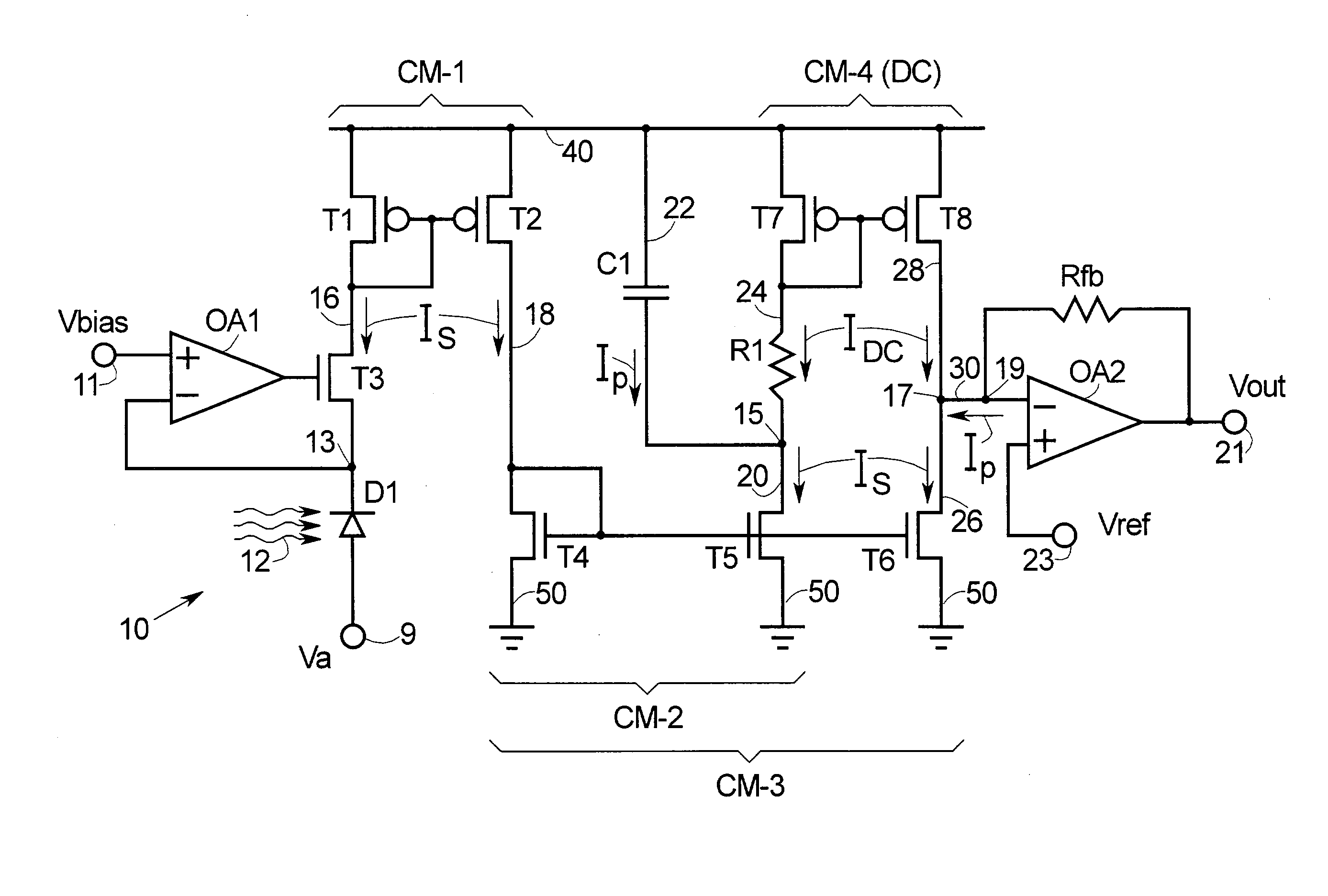
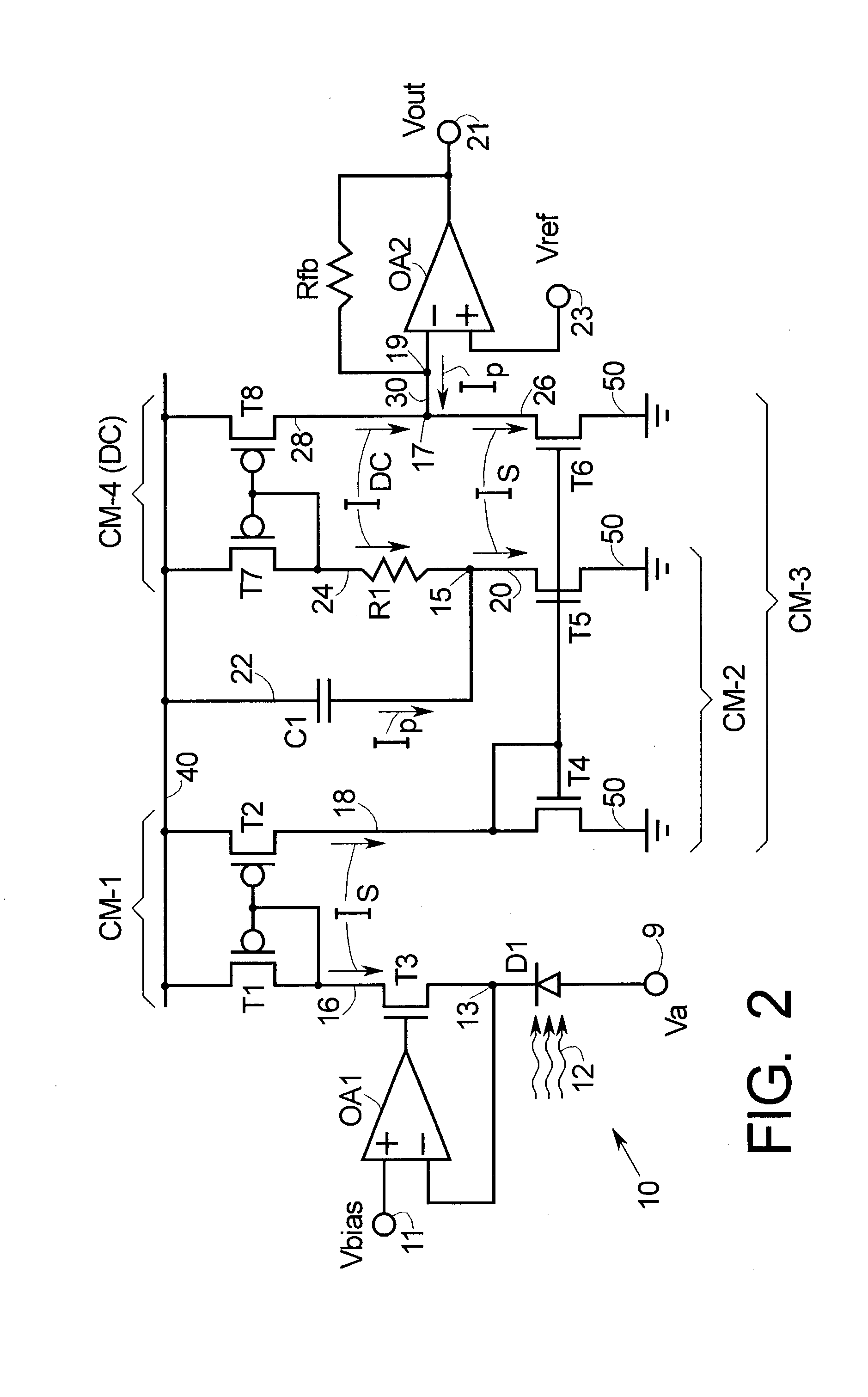
FIG. 2 is a simplified schematic diagram of electronic circuit 10 for separating the DC and AC components of a composite DC+AC signal, according to the present invention. For convenience of explanation, circuit 10 is illustrated for the circumstance where the composite electrical signal Is originates from photo-detector D1, but persons of skill in the art will understand that other sources of the composite signal may be used and that the present invention is not limited by the choice of composite signal source.

Composite optical signal 12 falls on photo-detector D1, thereby modulating its conductivity in accordance with alterations, for example...


PUM


Abstract

Methods and apparatus are provided for separating DC and AC components of a composite signal Is=Idc+Iac from a current source, e.g., a photodiode current source. Four current mirrors CM-1 . . . CM-4 are used with common branches and overlap. CM-1 through CM-3 mirror Is and CM-4 mirrors Idc where Iac has been removed by a frequency selective branch. Outputs of the Cm-3 and Cm-4 are combined at a node to provide a signal proportional substantially only to Iac. Complementary devices are used where Cm-1 and Cm-4 are of one type and Cm-2 and Cm-3 are of opposite type. The arrangement allows detection of AC signals (e.g., pulses) that are orders of magnitude smaller than the DC background. An I-to-V converter with a large feedback resistance is used at the output to produce a comparatively large voltage output proportional to Iac.

Description

FIELD OF THE INVENTION The present invention generally relates to means and methods for removing a substantially direct current (DC) signal so that a superposed alternating current (AC) signal can be more easily detected, and more particularly relates to removing a DC signal so a small superposed pulse signal can more easily be detected. BACKGROUND OF THE INVENTION There are many situations in electronic applications where an AC or pulse signal of interest is superposed on a comparatively large substantially DC signal. As used herein the term “direct current” and the abbreviation DC are intended to include any current signal that is slowly varying compared to the signal of interest. Similarly, the term “alternative current” and the abbreviation AC are intended to include any current signal that is varying rapidly compared to a background DC signal. The term AC is intended to include pulse signals and vice versa. The classical method of removing DC from a composite DC+AC signal is...

Claims


Application Information

Patent Timeline
Patent Type & Authority Applications(United States)
IPC IPC(8): G05F3/26H03F3/08H03K3/00H03K5/003H03K5/08H03K17/00
CPCG05F3/262H03K5/08H03K5/003H03F3/082
Inventor BERNARDSON, PETER S.
Owner MEDTRONIC INC
Why Eureka
Try Eureka