Half-bridge circuit

a half-bridge circuit and circuit technology, applied in the field of half-bridge circuits, can solve the problems of increased losses, negative feedback associated with undesirable switching losses, and switching losses during normal operation of the half-bridge circuit, so as to prevent leakage and/or line inductance, and reduce losses

Inactive Publication Date: 2005-04-14
INFINEON TECH AG
View PDF5 Cites 38 Cited by
  • Summary
  • Abstract
  • Description
  • Claims
  • Application Information

AI Technical Summary

Benefits of technology

[0026] One particularly advantageous embodiment variant of the invention provides for the auxiliary electrode of the first switching transistor to be connected to the line to the phase output precisely at that distance from the second electrode of the first switching transistor at which the value of the inductance located in the connection path between the second electrode of the first switching transistor and the auxiliary electrode of the first switching transistor corresponds precisely to that value which is required for predetermined limitation of the turn-off speed of the first switching transistor by means of inductive negative feedback. A particularly discrete component therefore does not need to be provided. It suffices to select a favorable terminal point taking into account the line / leakage inductance of the phase output line connected to the second electrode.
[0027] According to the invention, provision is made for the line to the phase output to be connected essentially directly to the second electrode of the first switching transistor. This measure prevents leakage and / or line inductances from still being situated in the (normal operation) commutation circuit (as in accordance with the prior art).
[0028] According to the invention, provision is also made for the anode of the first diode to be directly connected to the auxiliary electrode of the first switching transistor. This measure makes it possible to further reduce the losses during normal operation.

Problems solved by technology

In the case of normal operation, however, too much negative feedback is associated with increased losses, which is undesirable.
Negative feedback that is associated with undesirable switching losses therefore takes place.
Although the abovementioned embodiment has fundamentally proven successful, the negative feedback of the driving of the two switching transistors that is needed to limit the turn-off speed of the latter in the event of a short circuit leads to switching losses during normal operation of the half-bridge circuit.

Method used


Image

  • Half-bridge circuit
  • Half-bridge circuit
  • Half-bridge circuit

Examples


Embodiment Construction

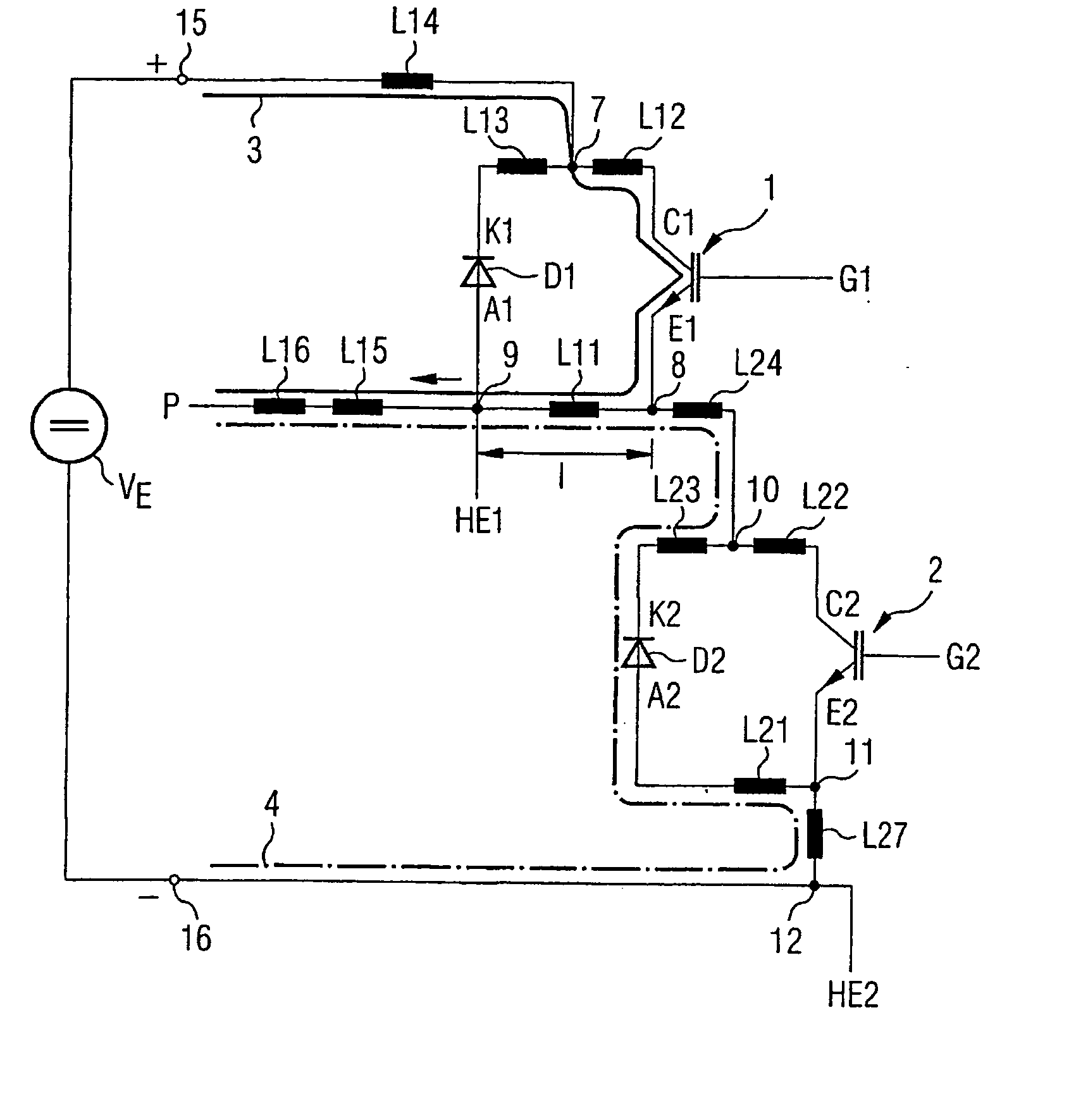
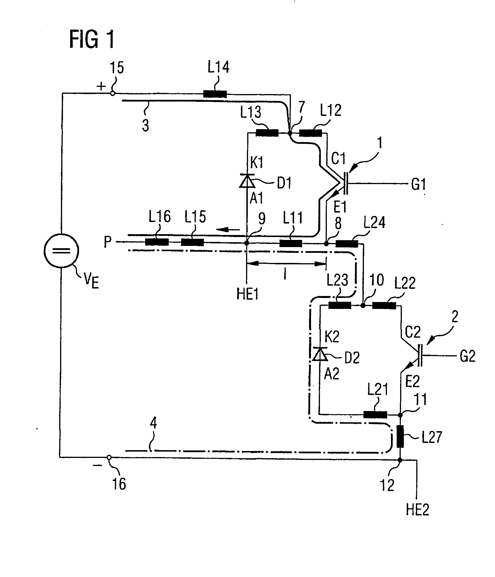
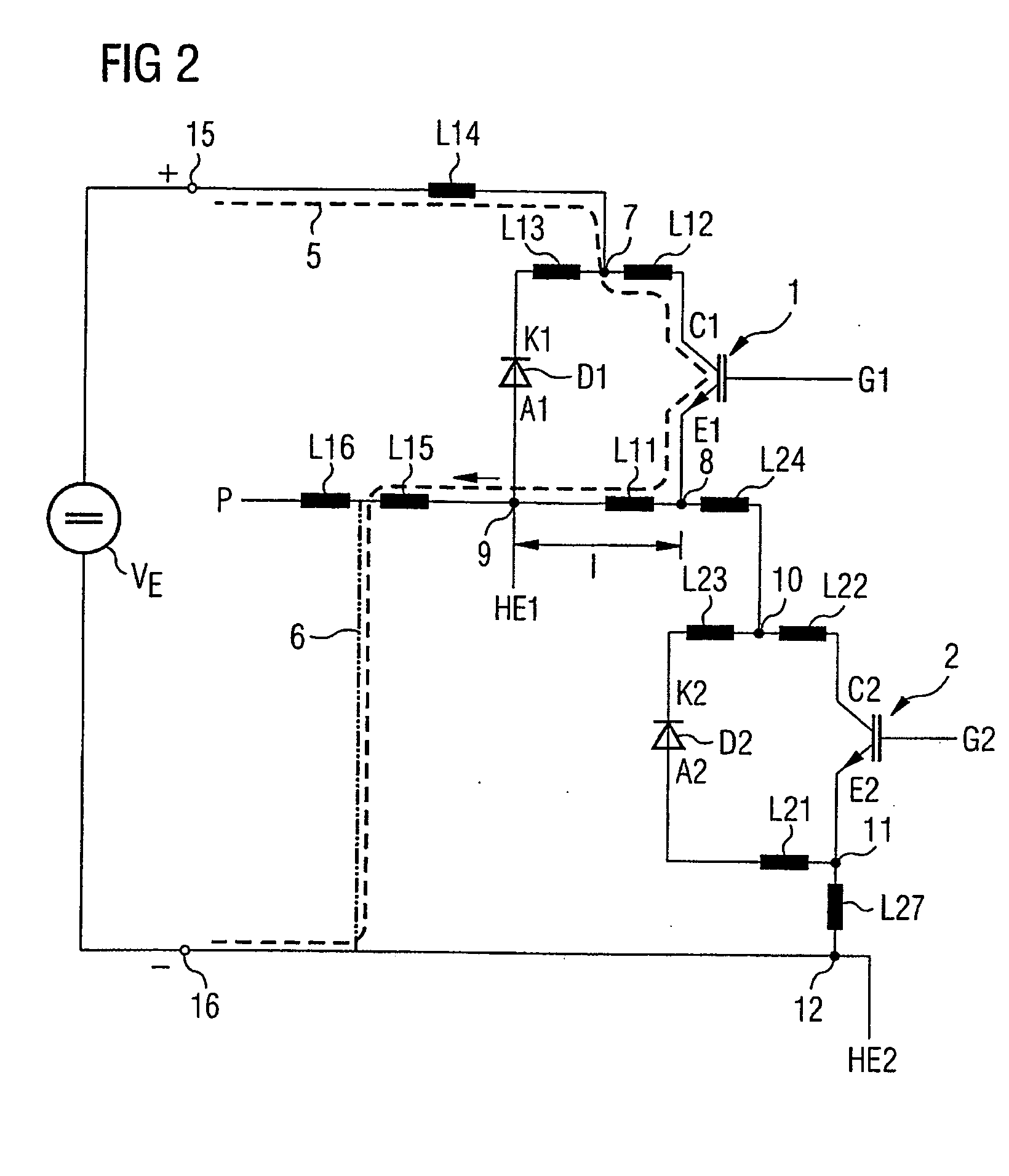
[0033]FIGS. 1 and 2 show a modification according to the invention of the half-bridge circuit (in accordance with the prior art) that is illustrated in FIG. 3 and is described in detail above. The individual components of the half-bridge circuits that are identically present in all the FIGS. 1 to 3 of the drawing are illustrated, for the sake of easier understanding, in the form of circuit symbols which have been provided with the same reference symbols. As in FIG. 3 of the drawing, the leakage and line inductances that are present are also symbolized here by circuit symbols of discrete coils.

[0034] Accordingly, the half-bridge circuit that is shown in FIGS. 1 and 2 and is based on two insulated gate bipolar transistors and two diodes has two input terminals 15 and 16—via which an input DC voltage VE can be supplied—and a phase output P, at which an AC voltage can be tapped off.

[0035] The first input terminal 15 is connected to the node 7 via the (line / leakage) inductance L14. The...


PUM


Abstract

A half-bridge circuit, in which an input signal that is applied between two input terminals can be picked up at a phase output comprises two switching transistors controlled by a respective control signal that is applied between a control electrode and an auxiliary electrode and two diodes. The first input terminal is connected to the first electrode of the first switching transistor and to the first diode's cathode. A second electrode of the first switching transistor is connected to the first diode's anode by means of the phase output, via a line, to a first electrode of the second switching transistor and to a cathode of the second diode. A second electrode of the second switching transistor is connected to an anode of the second diode and to the second input terminal. The auxiliary electrode of the first switching transistor is connected to the line of the phase output.

Description

CROSS REFERENCE TO RELATED APPLICATION [0001] This application is a continuation of copending International Application No. PCT / EP03 / 04096 filed Apr. 17, 2003 which designates the United States, and claims priority to German application no. 102 19 760.1 filed May 2, 2002. TECHNICAL FIELD OF THE INVENTION [0002] The present invention relates to a half-bridge circuit. BACKGROUND OF THE INVENTION [0003] Half-bridge circuits are used quite generally to generate an AC signal from a DC voltage that is supplied on the input side. When connected up in an appropriate manner, half-bridge circuits of this type may also be used to generate polyphase AC signals, in particular also three-phase current signals. The output-side (if appropriate polyphase) AC signal is then supplied to a motor, for example. [0004] A multiplicity of variations of half-bridge circuits are known in accordance with the prior art. Half-bridge circuits on which the invention is based are essentially based on two power tran...

Claims


Application Information

Patent Timeline
Patent Type & Authority Applications(United States)
IPC IPC(8): H02M7/538H03K17/082H03K17/16
CPCH02M7/538H03K17/168H03K17/0828
Inventor MUNZER, MARK NILSTSCHIRBS, ROMAN LENNART
Owner INFINEON TECH AG
Why Eureka
Try Eureka