Symmetric planar inductor

a planar inductor and symmetry technology, applied in the field of symmetric inductors, can solve the problems of increasing the a adding undesired capacitive coupling, and degrading the signal quality, so as to preserve the symmetry of the inductor, reduce the capacitive effects of conductor crossover, and reduce the effect of the capacitive

Inactive Publication Date: 2005-04-14
HRL LAB
View PDF20 Cites 25 Cited by
  • Summary
  • Abstract
  • Description
  • Claims
  • Application Information

AI Technical Summary

Benefits of technology

[0007] In one aspect, the present invention relates to a inductor which is substantially symmetric and thus does not exhibit signal degradations due to asymmetry of the inductor. The symmetric inductor comprises concentric windings of different sizes or effective diameters, and winding crossov

Problems solved by technology

Any asymmetry in circuits using differential signals (differential circuits) has the effect of degrading the signal quality, and is thus very undesirable.
Further, this configuration requires the

Method used


Image

  • Symmetric planar inductor
  • Symmetric planar inductor
  • Symmetric planar inductor

Examples


Embodiment Construction

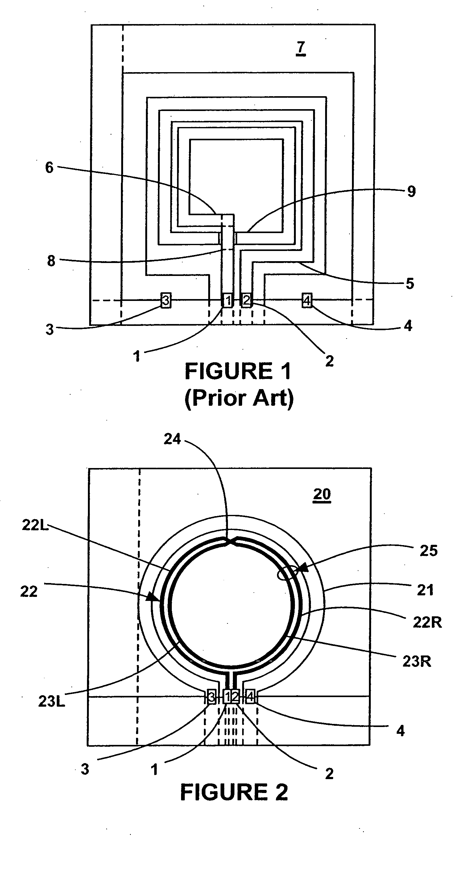
[0014] Referring to FIG. 2, a planar symmetric inductor 20 in accordance with an embodiment of the present invention is shown. A planar inductor is an inductor whose plurality of windings preferably occupy a common plane except for the cross-over or cross-under points. The inductor 20 can be connected to other components of a circuit by terminal 1 and terminal 2, while terminal 3 and terminal 4 are ground terminals. The inductor 20 comprises an inductor winding 25 made of a conductive material, the winding 25 including concentric outer circular winding 22 and inner circular winding 23. The inductor 20 also comprises a circular peripheral conductor 21 which forms a ground plane that terminates the electric fields and makes the inductor 20 a guided wave structure. The circular peripheral conductor 21 is concentric with circular windings 22 and 23 and has diameter greater than that of circular windings 22 and 23. As shown in FIG. 2, peripheral conductor 21 is preferably disposed at the...


PUM


Abstract

A substantially symmetric inductor comprising a plurality of windings, at least one conductor crossover, and a peripheral conductor disposed at the periphery of the plurality of windings, the plurality of windings having a generally symmetric shape, each of the plurality of windings having a center and being of a different size from other ones of the plurality of windings, the peripheral conductor being generally symmetric and having a center, the plurality of windings and the peripheral conductor being substantially concentric, the conductor crossovers being disposed such that the symmetry of the inductor in substantially preserved. A method of winding an inductor such that the inductor is substantially symmetric about a center of the inductor, whereby signal degradation due to asymmetry of the inductor is substantially minimized.

Description

CROSS REFERENCE TO RELATED APPLICATION [0001] This application claims the benefit of U.S. Patent Provisional Patent Application Ser. No. 60 / 412,283 filed Sep. 20, 2002, the disclosure of which is hereby incorporated herein by reference.TECHNICAL FIELD [0002] This invention relates to the field of inductors which are used in integrated circuits. In particular, this invention relates to symmetric inductors particularly adequate for use in circuits using differential signals. The inductors winding preferably have either a spiral or a spiral-like planar configuration. BACKGROUND OF THE INVENTION [0003] Patents relating to inductors abound in the prior art. However, most such patents refer to standard, asymmetric spiral inductors, and disclose various methods of improving characteristics of these spiral inductors, such as increasing Q=Ws / Wd (where Ws is the energy stored and Wd is the energy dissipated in the inductor per cycle) or reducing the size of the inductors. Examples of inductor...

Claims


Application Information

Patent Timeline
IPC IPC(8): H01F17/00H01F27/34H01L23/522
CPCH01F17/0006H01F27/34H01L2924/09701H01L23/5227H01F2017/0046H01L2924/0002H01L2924/00
Inventor RAGHAVAN, GOPALCASE, MICHAEL G.
Owner HRL LAB
Why Eureka
Try Eureka