Image display unit

a display unit and image technology, applied in the field of hold type image display units, can solve the problems of after-image generation, slow response speed of liquid crystal display units, and hold type display units such as liquid crystal display units, and achieve the effect of reducing moving image blurriness

Active Publication Date: 2005-04-14
JVC KENWOOD CORP A CORP OF JAPAN
View PDF9 Cites 77 Cited by
  • Summary
  • Abstract
  • Description
  • Claims
  • Application Information

AI Technical Summary

Benefits of technology

[0009] In view of the above-described drawbacks, it is an object of the present invention to provide an image display unit which can reduce moving image blurriness without impairing an advantage of the hold type display which can perform display without flicker.

Problems solved by technology

Since a response speed of the liquid crystal display unit is slow, the liquid crystal display unit has a problem that an after-image is generated when a moving image is displayed.
The hold type display unit such as a liquid crystal display unit, however, cannot solve blurriness (which will be referred to as a moving image blur) of a moving image caused due to an influence of a visual system integration owing to hold display itself even if a response speed of the liquid crystal is increased.
The first method has a drawback (first problem) that means for shutting a backlight in synchronization with a video signal is required and display without flicker which is an advantage of the hold type display is deteriorated.
The second method has an disadvantage (second problem) that a sampling frequency of a video signal and a writing speed of the liquid crystal must be respectively doubled in order to double a frame frequency, which imposes a great burden on an operating speed of a circuit or a connection interface between circuits, thereby involving an actual difficulty.

Method used


Image

  • Image display unit
  • Image display unit
  • Image display unit

Examples


first embodiment

[0036] First Embodiment

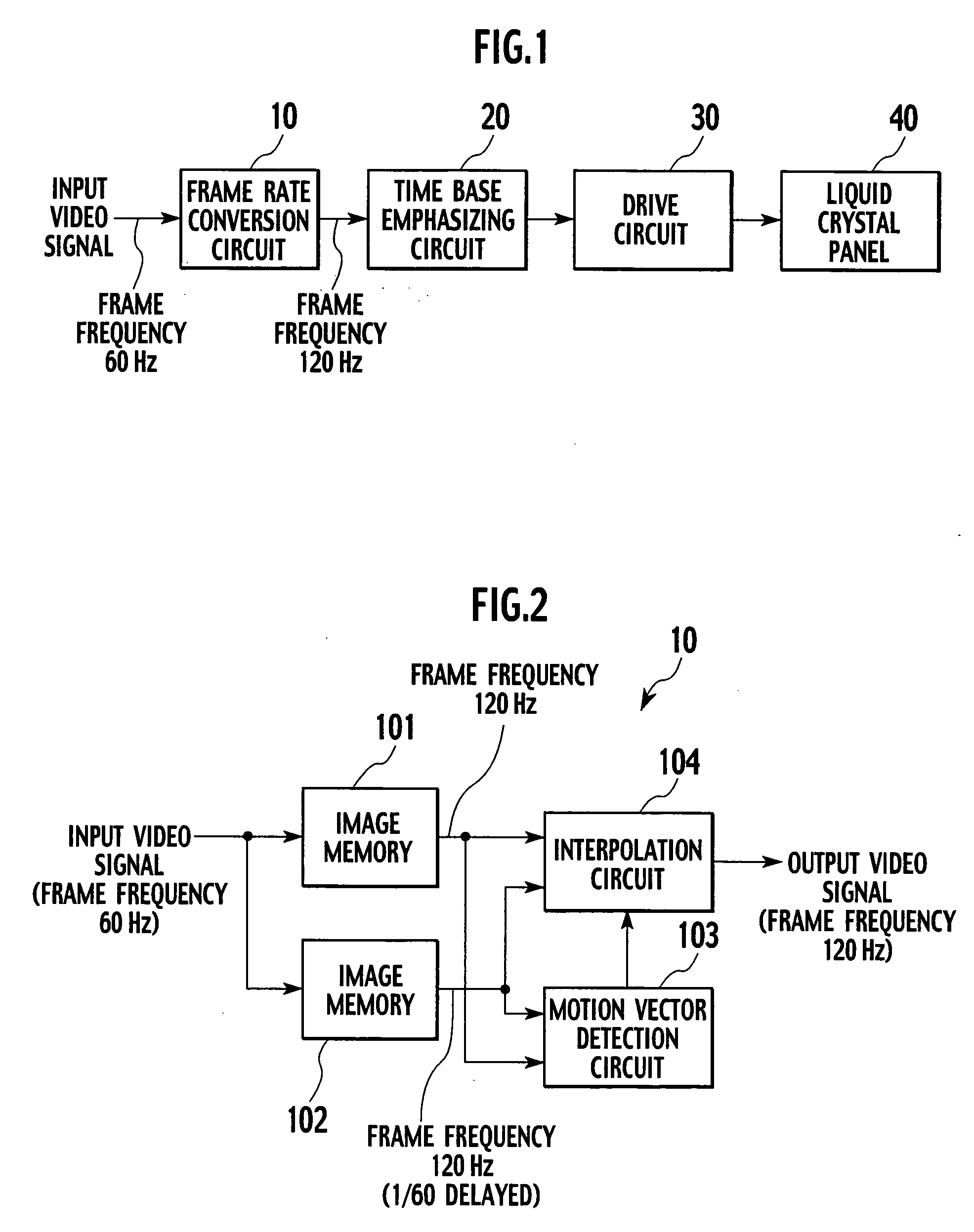
[0037]FIG. 1 is a block diagram showing a first embodiment of an image display unit according to the present invention.

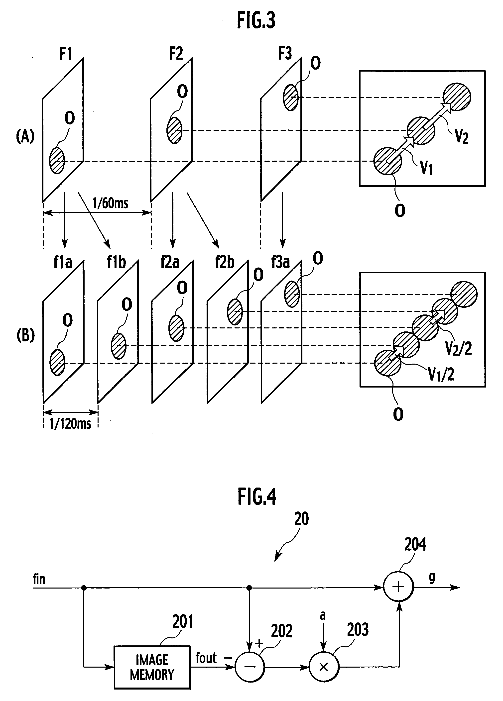
[0038] The first embodiment solves the first problem mentioned above. In FIG. 1, a video signal is input to a frame rate conversion circuit 10. The frame rate conversion circuit 10 converts a frame frequency (vertical frequency) of the input video signal into a doubled frequency, and outputs the converted signal. In the first embodiment and second and third embodiments which will be described later, the frame frequency of the input video signal (original signal) is converted into a m / n-fold frequency. Here, m is an integer of 2 or more, n is an integer of 1 or more, and conditions of m>n are satisfied. In the first to third embodiments, m=2 and n=1 are achieved, and the frame frequency 60 Hz of the input video signal is converted into 120 Hz.

[0039] Incidentally, in regard to a video signal subjected to 2:1 interlace at a frame frequency of 3...

second embodiment

[0054] Second Embodiment

[0055]FIG. 7 is a partial block diagram showing a second embodiment of an image display unit according to the present invention. FIG. 8 is a timing chart illustrating an operation of the second embodiment.

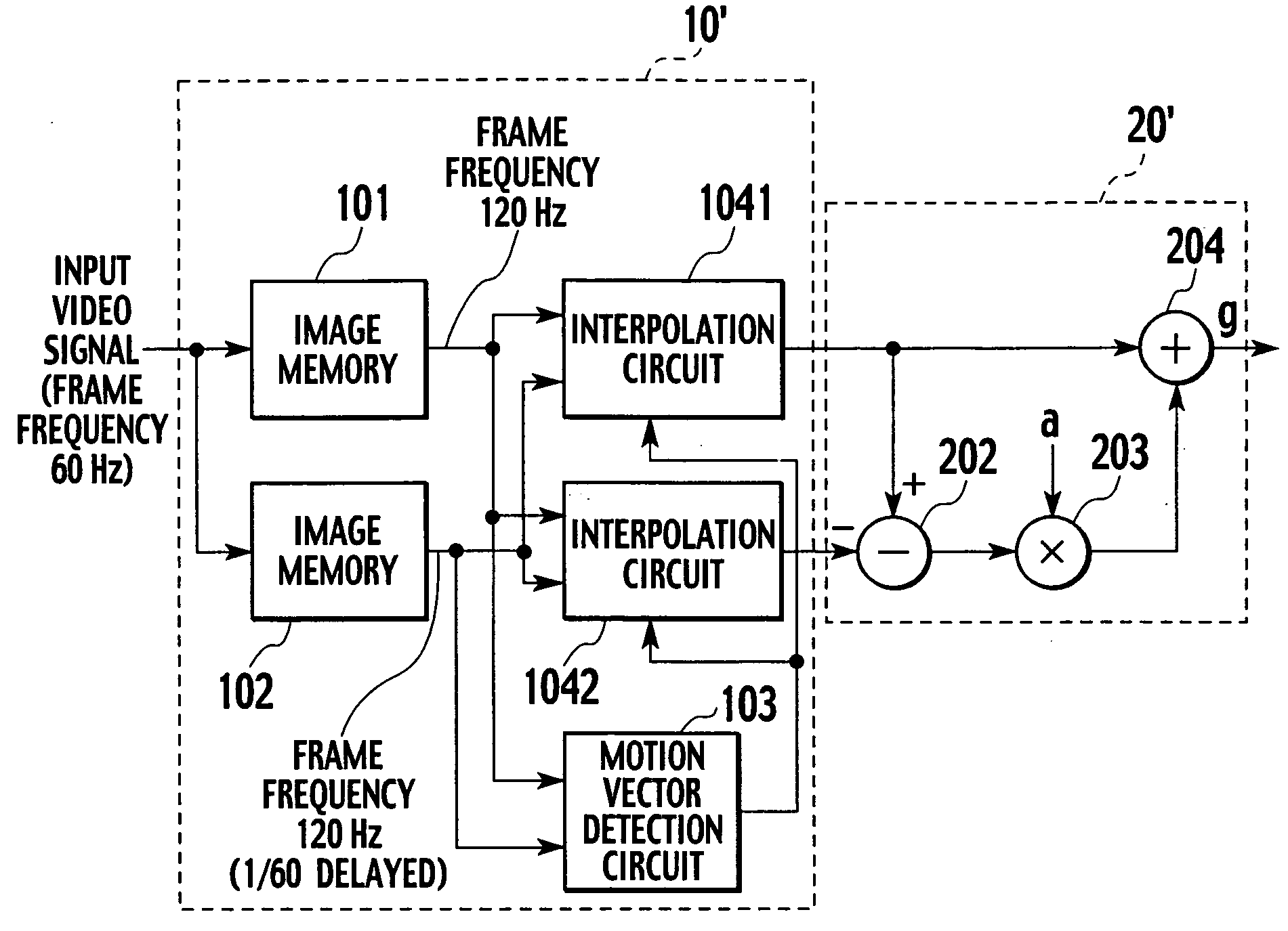
[0056] The second embodiment is obtained by improving the concrete structures of the frame rate conversion circuit 10 and the time base emphasizing circuit 20 in FIG. 1. Specifically, the image memory 201 in FIG. 4 is eliminated, and the concrete structure of the frame rate conversion circuit 10 is changed in accordance with the elimination of the image memory 201. The frame rate conversion circuit and the time base emphasizing circuit in the second embodiment will be referred to as a frame rate conversion circuit 10′ and a time base emphasizing circuit 20′. In FIG. 7, like reference numerals denote parts equal to those in FIGS. 2 and 4, and the explanation of these parts may be appropriately eliminated in some cases.

[0057] In FIG. 7, image data output fro...

third embodiment

[0062] Third Embodiment

[0063]FIG. 9 is a partial block diagram showing a third embodiment of the image display unit according to the present invention.

[0064] The third embodiment can be obtained by further simplifying the frame rate conversion circuit 10′ according to the second embodiment, and the frame rate conversion circuit in the third embodiment will be referred to as a frame rate conversion circuit 10″. In FIG. 9, like reference numerals denote parts equal to those shown in FIGS. 2, 4 and 7, and the explanation thereof may be appropriately eliminated in some cases.

[0065] Image data output from image memories 101 and 102 are supplied to a motion vector detection circuit 103, an interpolation circuit 104 and selectors 1051 and 1052. The image data which was subjected to motion compensation interpolation and output by the interpolation circuit 104 is supplied to the selectors 1051 and 1052.

[0066] The image data output from the selector 1051 is supplied to a subtracter 202 and...


PUM


Abstract

An active matrix type display panel is a hold type display panel which has a plurality of pixels arranged in a matrix form, and holds and displays an electrical signal pixel by pixel for a predetermined time. A frame rate conversion circuit converts a video signal having a first vertical frequency (60 Hz) into a video signal having a second vertical frequency (120 Hz) which is m/n-fold (wherein m is an integer of 2 or more, n is an integer of 1 or more, and conditions of m>n are satisfied) of the first vertical frequency. A time base emphasizing circuit subjects an output from the frame rate conversion circuit to time base emphasis. A drive circuit displays the video signal having the second vertical frequency in a display panel.

Description

BACKGROUND OF THE INVENTION [0001] 1. Field of the Invention [0002] The present invention relates to a hold type image display unit as typified by a liquid crystal display unit, and more particularly, it relates to an image display unit which can reduce blurriness of a moving image. [0003] 2. Description of the Related Art [0004] As image display units, there are an impulse type display unit which strongly emits light in a moment that an image is written like a display unit using a cathode ray tube (CRT), and a hold type display unit which holds display from writing of an image to writing of an image of a next frame like an active matrix type display unit having a memory function per each pixel. As the active matrix type display unit, there is a liquid crystal display unit using a thin-film transistor (TFT). In the liquid crystal display unit, an image written in a pixel by a TFT and a capacitor arranged for each pixel is held for a fixed time. [0005] Since a response speed of the l...

Claims


Application Information

Patent Timeline
Patent Type & Authority Applications(United States)
IPC IPC(8): G09G3/36H04N5/44H04N7/01
CPCG09G3/3648G09G2320/0252G09G2320/0257G09G2320/0261H04N7/014G09G2340/0435G09G2340/16H04N7/0132G09G2320/106
Inventor AIBA, HIDEKIKUBOTA, KENJI
Owner JVC KENWOOD CORP A CORP OF JAPAN
Why Eureka
Try Eureka