Image forming apparatus

a technology of image forming apparatus and forming drum, which is applied in the direction of electrographic process apparatus, corona discharge, instruments, etc., can solve the problems of reducing the overall size the inability of the peripheral surface of the photoconductive drum to be uniformly charged, and the improper charge of the photoconductive drum, etc., to prevent the occurrence of carrier adhesion, improve the cleaning efficiency of the image forming apparatus, and output excellent images

Inactive Publication Date: 2005-04-14
CANON KK
View PDF7 Cites 16 Cited by
  • Summary
  • Abstract
  • Description
  • Claims
  • Application Information

AI Technical Summary

Benefits of technology

[0035] The present invention is made to solve the problems of the above described prior arts, and its primary object is to provide an image forming apparatus capable of always outputting excellent images.
[0036] Another object of the present invention is to prevent the phenomenon that developer adheres to a primary charging means while a developer charging means is cleaned.
[0037] Another object of the present invention is to better clean the roller of the primary charging means, across the entirety of its peripheral surface, provided that the charging member of the charging means is in the form of a roller.
[0038] Another object of the present invention is to prevent the occurrence of carrier adhesion in the developing means, during the cleaning of the developer charging means and primary charging means, by making the surface potential of the image bearing member uniform (at zero) across the entirety of the peripheral surface of the image bearing member.
[0039] Another object of the present invention is to improve the cleaning efficiency of an image forming apparatus having multiple image forming means, and also to reduce the length of the cleaning time thereof.
[0040] Another object of the present invention is to provide an image forming apparatus capable of always outputting superb images for a long period of time, by regularly cleaning its auxiliary charging means and primary charging means, based on the cumulative number Of the outputted prints, the cumulative length of exposure time, or the like.

Problems solved by technology

However, simply reducing in size a photoconductive drum, each of the processing means, and each of the various devices, which make up an image forming apparatus, has its limit in reducing an image forming apparatus in overall size.
The simple removal of the cleaning apparatus allows the residual toner remaining on the photoconductive drum after the transfer to directly adhere to the charge roller 102, making it impossible for the peripheral surface of the photoconductive drum to be uniformly charged; in other words, it causes the photoconductive drum to be improperly charged.
However, a cleaner-less system structured as described above suffers from the following problems.
Consequently, a photoconductive drum fails to be charged to the normal potential level, resulting in the formation of an image, the entirety of which is covered with fog.
This problem is likely to occur, in particular, when outputting an image having areas with a higher printing ratio, for example, solid areas.
Further, the greater the amount of the toner to be recovered by a toner charging brush, the more difficult it is for the entirety of the recovered toner to make contact with the toner charging brush; and therefore, the more difficult it is for the recovered residual toner to be entirely turned into hyped negative toner.
The portion of the residual toner, which slipped out of the toner charging brush, is unstable in the amount of electrical charge, as well as polarity.
Therefore, it is prone to adhere to a charge roller as it reaches the charge roller.
Therefore, as it adheres to a charge roller, it interferes with the charging of a photoconductive drum, making it difficult for the photoconductive drum to be uniformly charged to predetermined polarity and potential level.
Therefore, the amount of the toner which reaches a toner charging brush further increases, making it more difficult for a toner charging brush to turn the residual toner into hyped negative toner.
Therefore, more toner adheres to a charge roller, which results in the formation of a very foggy image, that is, an image with defects traceable to improper charging of a photoconductive drum.
However, this proposal also has a problem.

Method used


Image

  • Image forming apparatus
  • Image forming apparatus
  • Image forming apparatus

Examples


embodiment 1

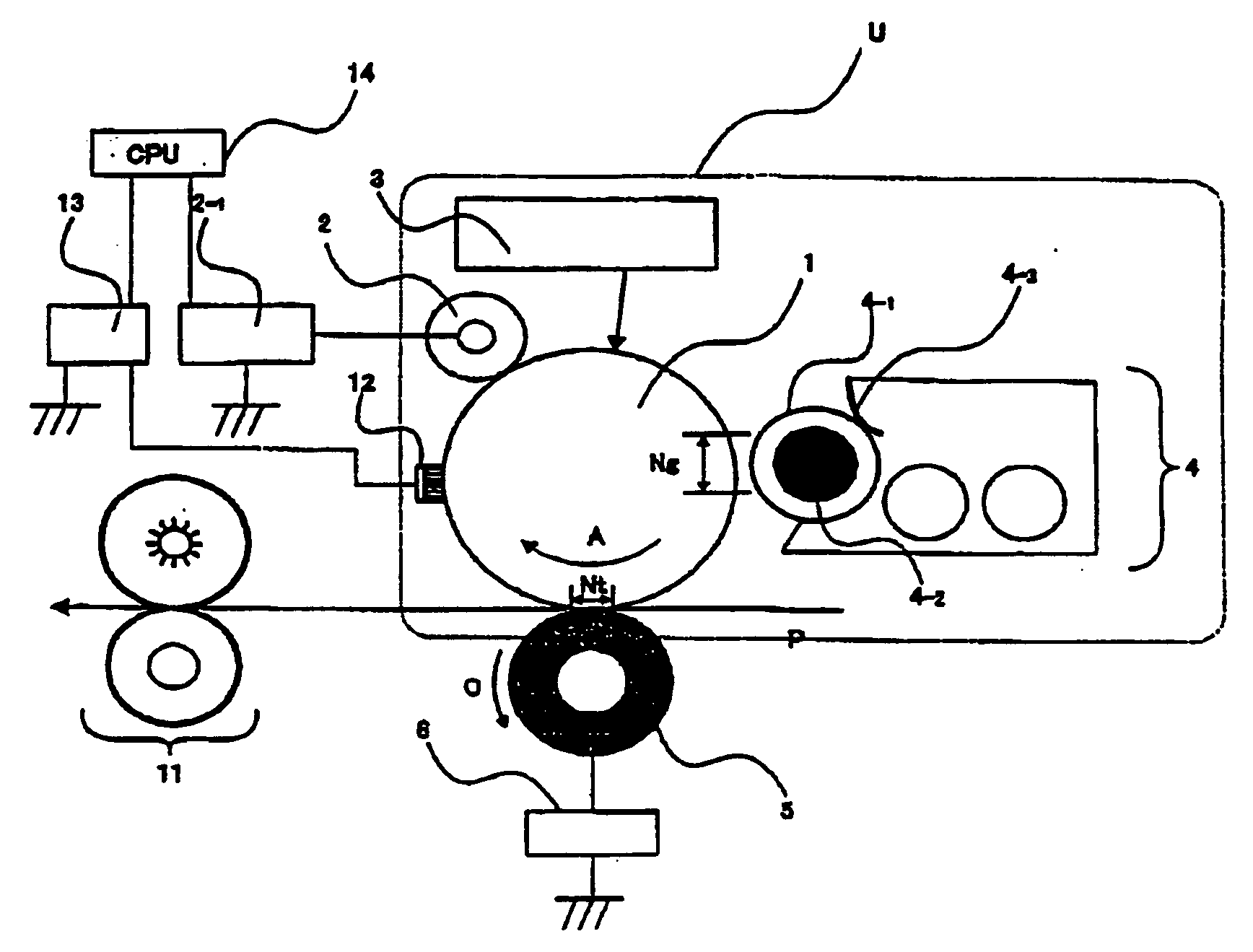
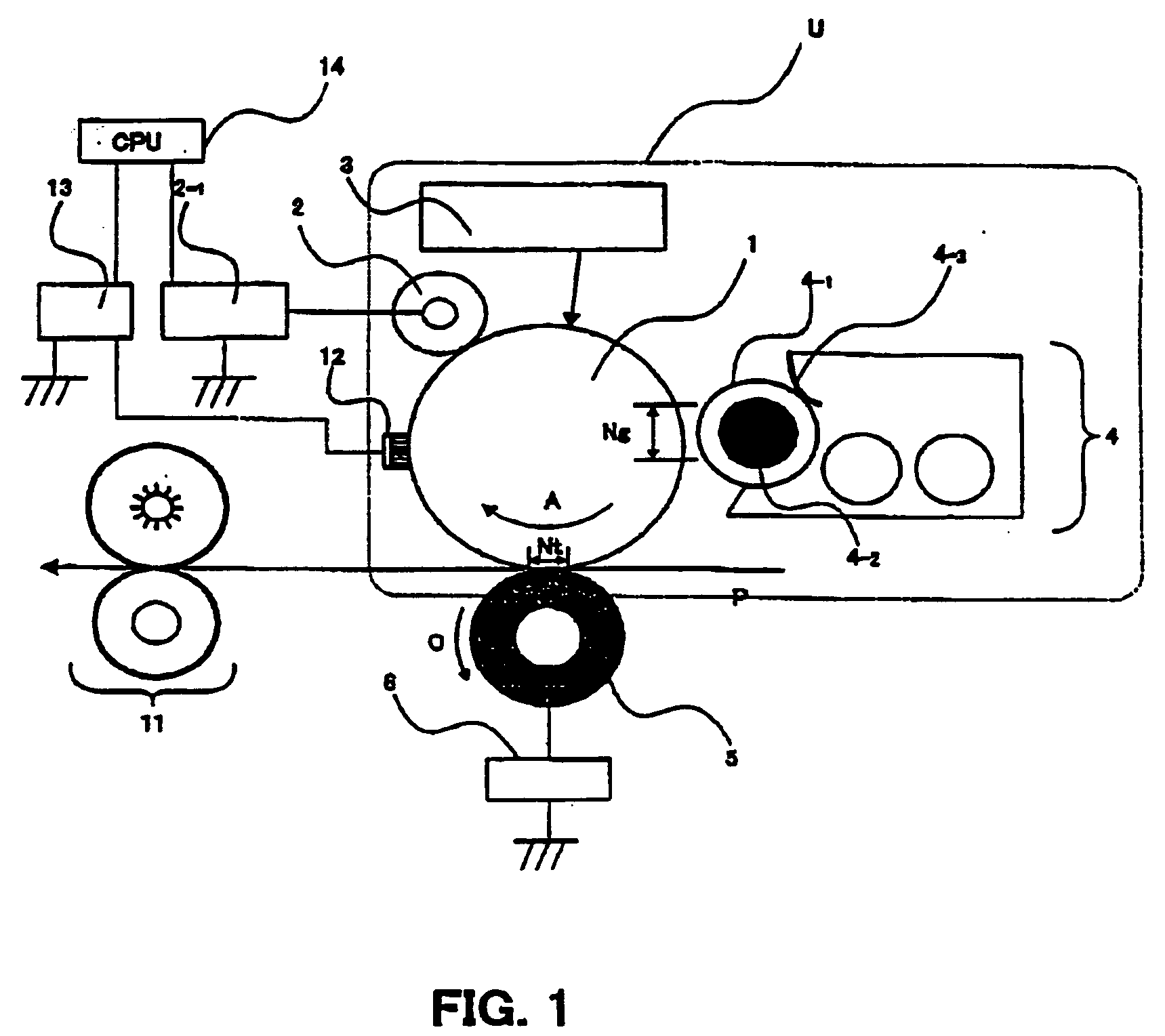
[0052] First, referring to FIGS. 1-3, the image forming apparatus in the first embodiment of the present invention will be described.

[0053] Referring to FIG. 1, a cylindrical photoconductive drum 1 as an image bearing member is being rotationally driven in the direction indicated by an arrow mark A at a peripheral velocity of 100 mm / sec. A charge roller 2 as a charging means is of a contact type, that is, a charge roller which is placed in contact with the photoconductive drum 1 to charge the photoconductive drum 1. It comprises an electrically conductive metallic core, an electrically conductive rubber layer coated on the peripheral surface of the metallic core, and a resistive layer coated on the peripheral surface of the rubber layer. It is rotated by the rotation of the photoconductive drum 1. To the metallic core of the charge roller 2, the combination of a DC voltage of −700 V and an AC bias with a peak-to-peak voltage of 1 KVp-p is applied from a charge bias power source 2-1...

embodiment 2

[0108] Next, the second embodiment of the present invention, which is a method for determining the timing with which a toner charging brush is cleaned, and the timing with which a charge roller in cleaned, in accordance with cumulative picture element count or cumulative exposure time, will be described.

[0109] The structure of the image forming apparatus in this embodiment is similar to that in the first embodiment. Therefore, its detailed description will not be given here.

[0110] First, referring to the flow chart given in FIG. 4, what kind of controls are executed with the use of the structural arrangement of this image forming apparatus will be described.

[0111] In the case of the flow chart given in FIG. 4, as a given printing job is started, the counting of the cumulative picture elements (which hereinafter will be referred to as pic-cell) or the cumulative exposure time, is started.

[0112] Then, it is continuously checked whether or not the value of the cumulative pic-cell c...

embodiment 3

[0116] The above described first and second embodiments were related to an image forming apparatus having only a single image formation unit. Instead, this embodiment is related to an image forming apparatus having multiple image formation units, as does a color image forming apparatus.

[0117] Except for the number of the image formation units, the structure and function of the image forming apparatus are the same as those in the first embodiment. Therefore, the structural components of the image forming apparatus in this embodiment, which are the same as those in the first embodiment, are given the same referential symbols as those given in the first embodiment, and they will be not described here.

[0118] As a typical image forming apparatus to which this embodiment of the present invention is applicable, an image forming apparatus such as the one shown in FIG. 5 that comprises four drums and an intermediary transfer belt will be described. It should be noted here that this embodim...


PUM


Abstract

An image forming apparatus includes an image bearing member; charging means for electrically charging the image bearing member while contacting to the image bearing member; transferring means for transferring a developed image on the image bearing member onto a transfer material; developer charging means for electrically charging a developer remaining on the image bearing member after the image is transferred, the developer charging means being disposed downstream of the transferring means and upstream of the charging means with respect to a moving direction of the image bearing member; and electric field forming means for forming a cleaning electric field in a direction of transferring the developer from the developer charging means onto a predetermined region of the image bearing member and for forming a cleaning electric field for transferring the developer from the charging means onto the image bearing member after the predetermined region of the image bearing member passes through a contact portion between the charging means and the image bearing member.

Description

FIELD OF THE INVENTION AND RELATED ART [0001] The present invention relate to an image forming apparatus, for example, a copying machine, a printer, a facsimileing machine, etc., which forms an image with the use of an electrophotographic method, an electrostatic recording method, or the like. [0002] As for this type of an image forming apparatus, that is, a copying machine, a printer, etc., which employs one of the electrophotographic image forming methods, those structured as shown in FIG. 8 have been available. [0003] In the case of this image forming apparatus, a photoconductive drum 101 is rotationally driven in the direction indicated by an arrow mark a (clockwise direction). As the photoconductive drum 101 is rotated, the following processes are sequentially carried out. [0004] First, the peripheral surface of the photoconductive drum 101 is uniformly charged by a charge roller 2 to which bias is being applied. Then, the charged portion of the surface of the photoconductive d...

Claims


Application Information

Patent Timeline
Patent Type & Authority Applications(United States)
IPC IPC(8): G03G21/00G03G15/02G03G15/08G03G15/16G03G21/10G03G21/14
CPCG03G2221/0005G03G15/0225
Inventor ISHIYAMA, TATSUNORIYODA, YASUOIIDA, KENICHI
Owner CANON KK
Why Eureka
Try Eureka