Fuel cell stack simulator

a fuel cell and simulator technology, applied in the direction of fuel cell details, fuel cell control, electric generators, etc., can solve the problems of limiting a variety of operating conditions to the breadboard, the performance of the bop is not yet guaranteed, and the fuel cell stack can deteriorate, so as to reduce the pressure of the supplied fuel gas, reduce the pressure of the supplied coolant, and reduce the pressure of the supplied air

Inactive Publication Date: 2005-04-14
HYUNDAI MOTOR CO LTD
View PDF4 Cites 16 Cited by
  • Summary
  • Abstract
  • Description
  • Claims
  • Application Information

AI Technical Summary

Benefits of technology

[0007] An exemplary fuel cell stack simulator according to the present invention includes an air flow field supplied with air and exhausting remains of the supplied air after heating the supplied air and reducing the pressure of the supplied air. This fuel cell stack should also include: a fuel flow field supplied with fuel gas and exhausting remains of the supplied fuel gas after heating the supplied fuel gas and reducing the pressure of the supplied fuel gas; a coolant flow field supplied with coolant and exhausting the supplied coolant after heating the supplied coolant and reducing the pressure of the coolant; a moisture-supplying field for supplying moisture into the fuel cell stack simulator; an air-consuming field connected to the air-supplying field for reducing the pressure of a portion of the air heated air; and a fuel-gas-consuming field connected to the fuel-gas-supply...

Problems solved by technology

However, when the newly developed BOP is applied to the breadboard, the performance of the BOP is not yet guaranteed such that the fuel cell stack can deteriorate.
Accordingly...

Method used


Image

  • Fuel cell stack simulator
  • Fuel cell stack simulator
  • Fuel cell stack simulator

Examples


Embodiment Construction

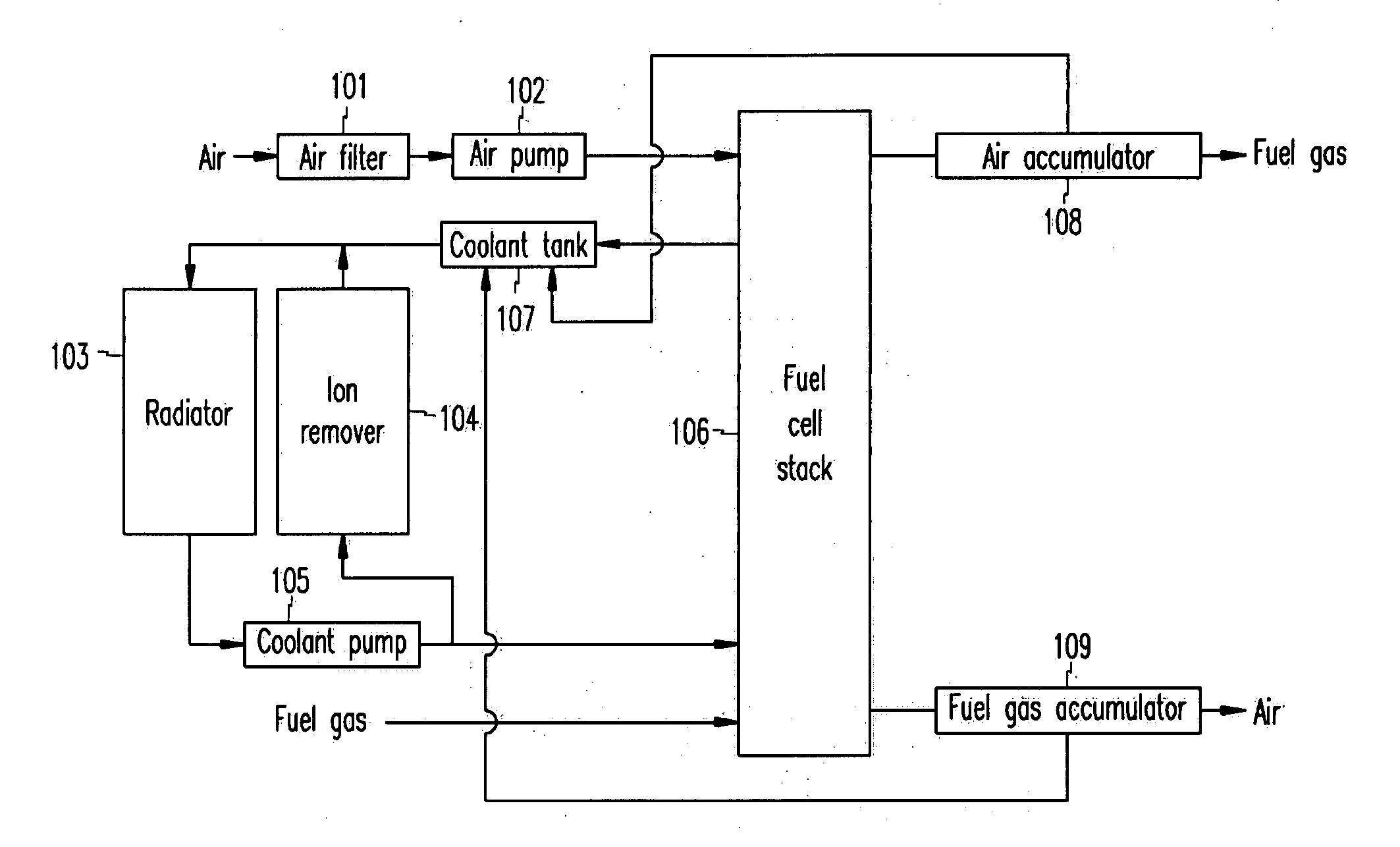
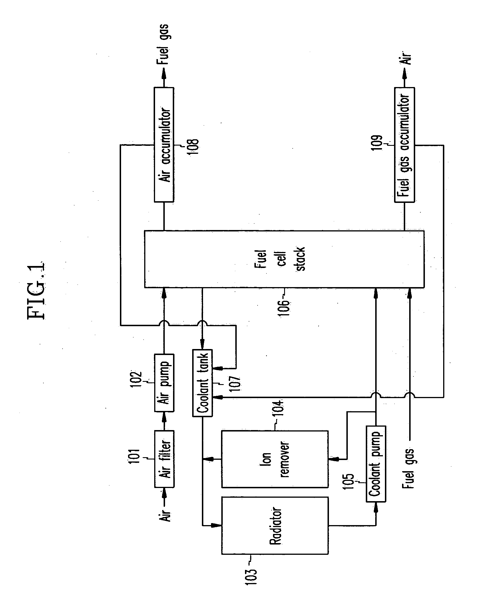
[0013]FIG. 1 illustrates a construction of a conventional fuel cell system.

[0014] As shown in FIG. 1, a fuel cell system has an air flow field, a fuel gas flow field, and a coolant flow field.

[0015] The air flow field has an air filter 101 for filtering induced air, an air pump 102 for applying a predetermined pressure to the introduced air, and an air accumulator 108 for condensation of air flowing from the fuel cell stack 106.

[0016] The air supplied to the air flow field flows through the air filter 101 from the air pump 102, and is inputted to the fuel cell stack 106 such that surplus air without having undergone electrochemical reaction is exhausted through the air accumulator 108.

[0017] The fuel gas supplied to the fuel gas flow field is inputted to the fuel cell stack 106 such that the surplus fuel gas without having undergone electrochemical reaction is exhausted through a fuel gas accumulator 109.

[0018] Meanwhile, the coolant circulates through the coolant flow field vi...


PUM


Abstract

A fuel cell stack simulator comprises an air flow field being supplied with air and exhausting the remains of the supplied air to outside after heating the supplied air and reducing the pressure of the supplied air. A fuel flow field is supplied with fuel gas and exhausts the remains of the supplied fuel gas to the outside after heating the supplied fuel gas and reducing the pressure of the supplied fuel gas. A coolant flow field is supplied with coolant and exhausts the supplied coolant to outside after heating the supplied coolant and reducing the pressure of the coolant. A moisture-supplying field supplies moisture into the fuel cell stack simulator. An air-consuming field is connected to the air-supplying field and derives a portion of the air heated air with reduced pressure. A fuel-gas-consuming field is connected to the fuel-gas-supplying field and derives a portion of the heated fuel gas with reduced pressure.

Description

CROSS-REFERENCE TO RELATED APPLICATIONS [0001] This application claims priority of Korean Application No. 10-2003-0070621, filed Oct. 10, 2003 , the disclosure of which is incorporated fully herein by reference. FIELD OF THE INVENTION [0002] This invention relates to a fuel cell system, and more particularly to a fuel cell stack stimulator which can be substituted for a fuel cell stack when estimating characteristics of BOP (Balance of Plant), such as an air blower, a coolant pump, a radiator, an accumulator, an ion remover, a mass flowmeter, and a plurality of sensors. BACKGROUND OF THE INVENTION [0003] When the fuel cell system is installed in a laboratory, the fuel cell system is called a “breadboard.” When the fuel cell stack or a BOP (Balance of Plant) of the fuel cell system is developed, the breadboard is installed and operated in order to estimate or inspect the characteristics of the fuel cell system. [0004] When evaluating the breadboard installed in the laboratory, a vari...

Claims


Application Information

Patent Timeline
IPC IPC(8): H01M8/00H01M8/02H01M8/04
CPCH01M8/04007H01M8/04044H01M8/04089Y02E60/50H01M8/04126H01M8/04298H01M8/04305H01M8/04097H01M8/04
Inventor PARK, YONG SEON
Owner HYUNDAI MOTOR CO LTD
Why Eureka
Try Eureka