Tool, apparatus, and method for precision polishing of lenses and lens molds

a technology for polishing tools and lenses, applied in the field of polishing tools, can solve the problems of high cost, high cost, and high cost of prior art process, and achieve the effects of low cost, high throughput, and high precision

Inactive Publication Date: 2005-04-14
OPTIPRO SYST
View PDF12 Cites 36 Cited by
  • Summary
  • Abstract
  • Description
  • Claims
  • Application Information

AI Technical Summary

Benefits of technology

[0029] The tools, apparatus, and method of the present invention are advantageous because they are simple and lower in cost compared to other approaches, and it can be adapted for the polishing of a variety of materials and shapes, particularly

Problems solved by technology

This prior art process is sufficient for many conventional low-precision lenses, but when the desired lens has a shape that is not spherical or plano and/or where such conventional methodologies cannot be applied e.g., aspherics, or where the lens has very high accuracy requirements, such prior art process is not sufficient.
The polishing tool wears quickly due to its small diameter, which results in the distinct disadvantages of a) typically very long polishing cycles; and b) because of quicker degradation of the small polishing foil it is much more difficult and costly to develop accurate corrective polishing routines.
Another disadvantage is due to the small spot diameter of the tool.
Material removal rates are typically very slow, since the performance is directly proportional to the size of the surfaces that are in contact during the polishing routine.
Although the MRF process has many attributes, such process also has some disti

Method used


Image

  • Tool, apparatus, and method for precision polishing of lenses and lens molds
  • Tool, apparatus, and method for precision polishing of lenses and lens molds
  • Tool, apparatus, and method for precision polishing of lenses and lens molds

Examples


Embodiment Construction

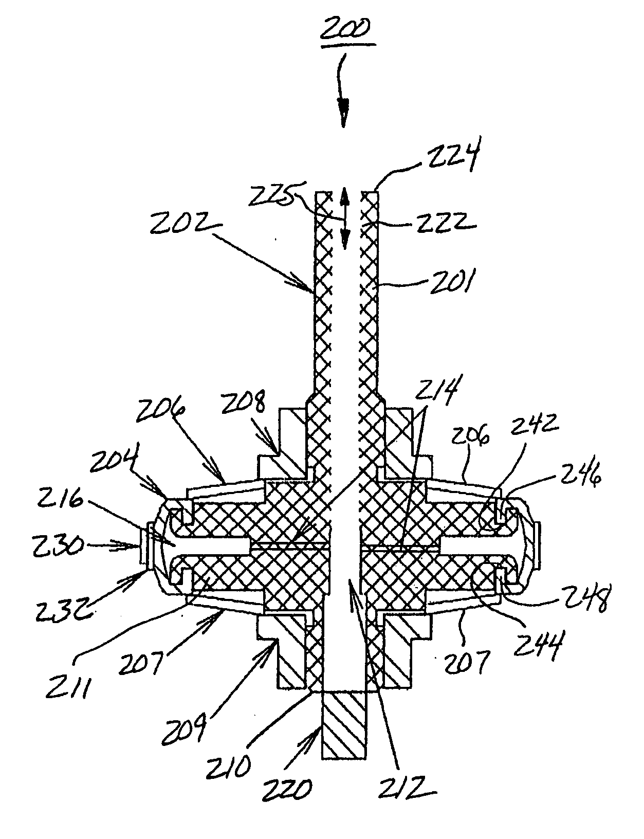
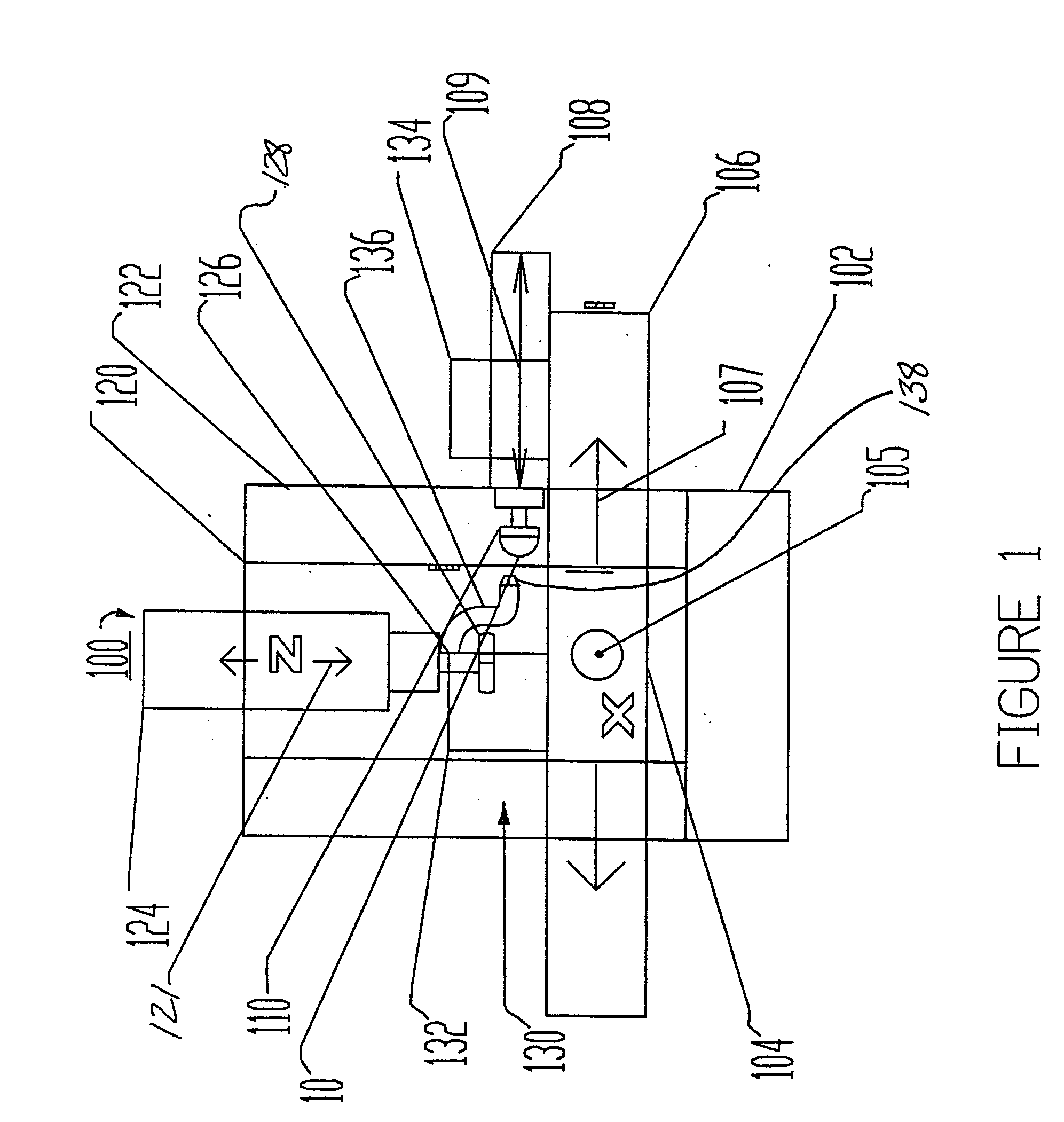
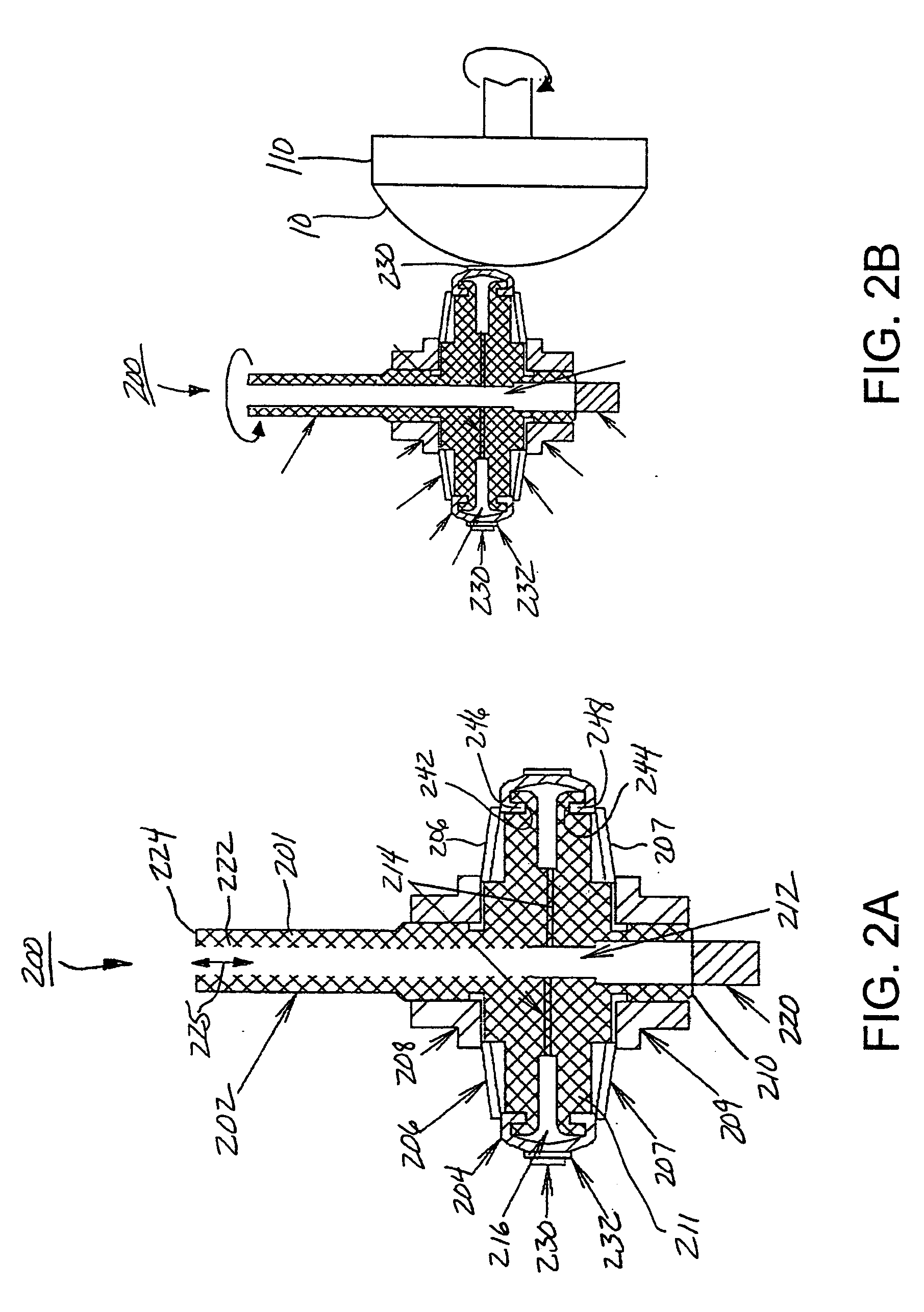
[0064] For a general understanding of the present invention, reference is made to the drawings. In the drawings, like reference numerals have been used throughout to designate identical elements. In describing the present invention, the following term(s) have been used in the description:

[0065] As used herein, the term figure error (or form error) is the measured global deviation from the desired surface shape e.g., a sphere, asphere or polynomial geometric shape.

[0066] As used herein, form error is a low frequency error. Traditionally in optics, irregularity and power are the two specifications that need to be considered. Irregularity is the deviation from a perfect surface. Power is the resulting average surface dimensions e.g., radius of curvature.

[0067] As used herein, the term zonal enhancement is meant to indicate a correction of the figure error, which is located symmetrically or asymmetrically at one specific location (zone) on the work piece. For example, if a cylindrica...


PUM

PropertyMeasurementUnit
Shapeaaaaaaaaaa

Abstract

A tool for polishing objects having a wide variety of materials and shapes including precision optical surfaces, injection mold inserts, and thin film coating dies. The tool has an elastic solid bladder with a curved surface, upon which is disposed an abrasive band. The curved bladder surface is produced by compressing the bladder between two parallel plates. The apparatus comprises a multi-axis computer controlled machine to which the tool is attached.

Description

CROSS-REFERENCE TO RELATED PATENT APPLICATIONS [0001] This application is a continuation-in-part of copending patent application U.S. Ser. No. 10 / 863,702, filed on Jun. 8, 2004, which is a continuation-in-part of copending patent application U.S. Ser. No. 10 / 439,833, filed on May 16, 2003, the disclosures of which are incorporated herein by reference.FIELD OF THE INVENTION [0002] A polishing tool for correcting surface errors, and for polishing objects comprising a wide variety of materials and shapes including precision optical surfaces and injection mold inserts. BACKGROUND OF THE INVENTION [0003] This invention relates to tools, an apparatus, and a method for correcting figure errors, and for polishing a wide variety of materials and shapes including but not limited to precision optical surfaces, injection mold inserts, thin film coating dies, and the like. The method of the present invention provides for improving and further finishing of any surface, ranging from a relatively r...

Claims


Application Information

Patent Timeline
IPC IPC(8): B24B13/01B24B13/06
CPCB24B13/06B24B13/01
Inventor BECHTOLD, MICHAEL J.
Owner OPTIPRO SYST
Why Eureka
Try Eureka