Bus device that concurrently synchronizes source synchronous data while performing error detection and correction

a bus device and data synchronization technology, applied in the direction of instruments, coding, code conversion, etc., can solve the problems of adding to the latency associated with data transfer in the system, affecting the operation of the system,

Inactive Publication Date: 2005-04-14
HEWLETT PACKARD DEV CO LP
View PDF3 Cites 45 Cited by
  • Summary
  • Abstract
  • Description
  • Claims
  • Application Information

AI Technical Summary

Problems solved by technology

Such errors may have a detrimental effect on the operation of the system.
Error detection and correction logic may be included but undesirably may add to the latency associated with data transfers in the system.

Method used


Image

  • Bus device that concurrently synchronizes source synchronous data while performing error detection and correction
  • Bus device that concurrently synchronizes source synchronous data while performing error detection and correction
  • Bus device that concurrently synchronizes source synchronous data while performing error detection and correction

Examples


Embodiment Construction

[0010] The following discussion is directed to various embodiments of the invention. Although one or more of these embodiments may be preferred, the embodiments disclosed should not be interpreted, or otherwise used, as limiting the scope of the disclosure, including the claims. In addition, one skilled in the art will understand that the following description has broad application, and the discussion of any embodiment is meant only to be exemplary of that embodiment, and not intended to intimate that the scope of the disclosure, including the claims, is limited to that embodiment.

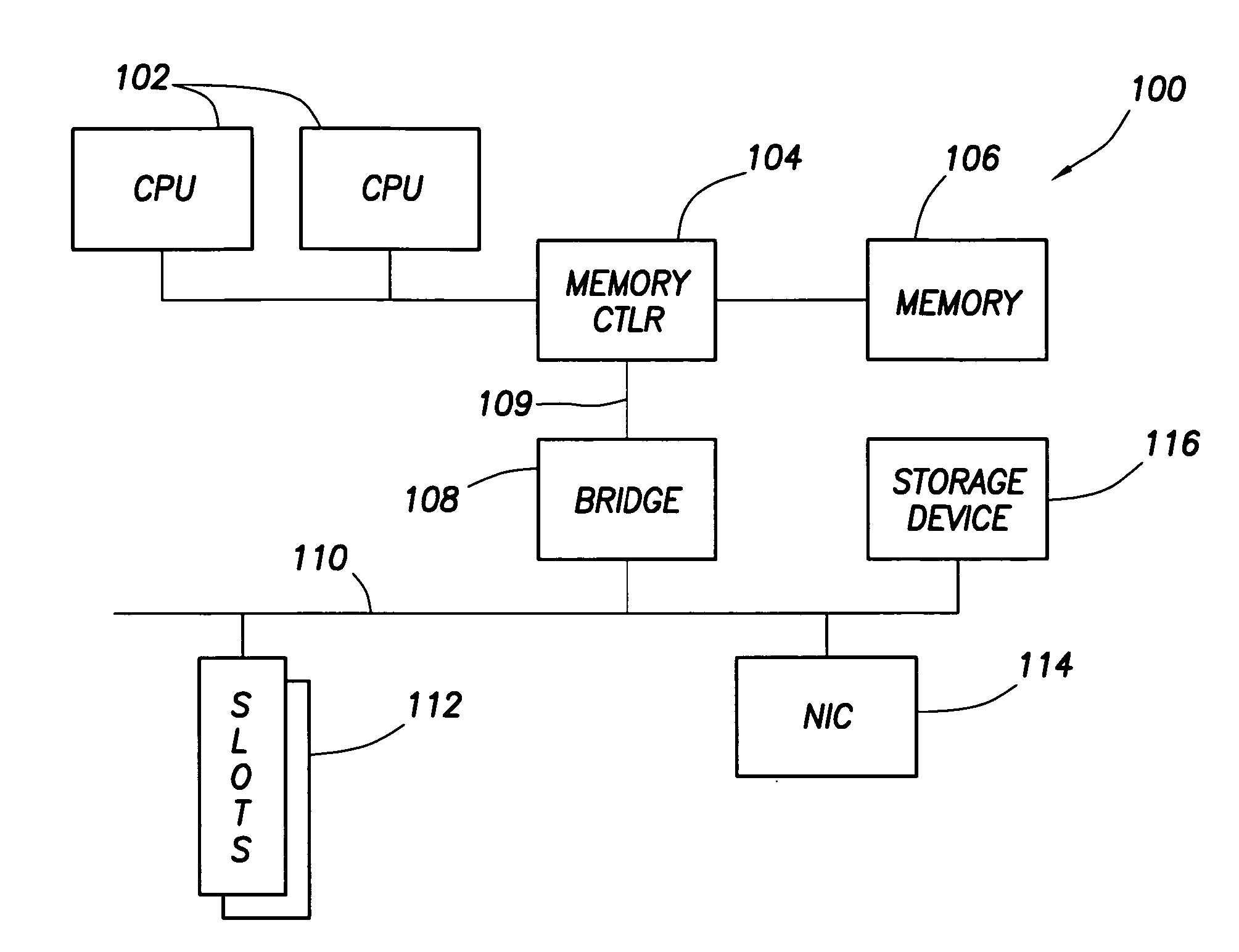
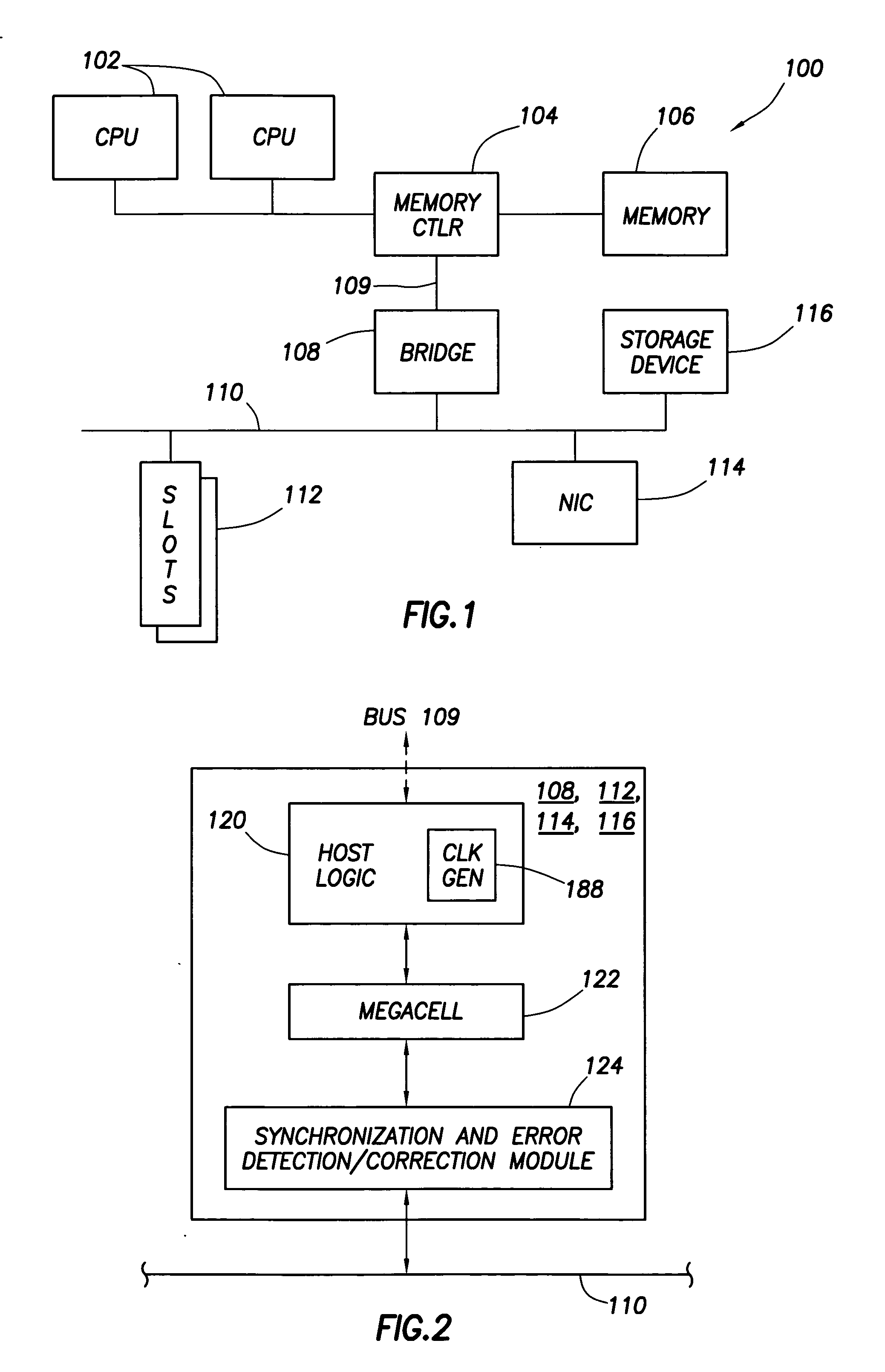
[0011] Referring to FIG. 1, a system 100 is shown in accordance with exemplary embodiments of the invention. System 100 may be representative of a wide variety of electronic systems such as a computer. As shown, the system 100 may comprise one or more central processing units (“CPUs”) 102, a memory controller 104, memory 106, a bridge 108, and one or more other devices such as a network interface controll...


PUM


Abstract

A bus device comprises a clock generator that is adapted to generate a clock signal for internal use by the bus device, data synchronizing logic that is adapted to synchronize source synchronous data that the bus device receives from the bus to the bus device's clock signal, and error detection and correction logic coupled to the data synchronizing logic. The error detection and correction logic is adapted to detect and correct errors associated with the data received from the bus concurrently while the data synchronizing logic synchronizes source synchronous data received from the bus to the clock signal.

Description

BACKGROUND [0001] In many types of electronic systems, electronic components within the system may be capable of transmitting digital data to and receiving digital data from other components. For example, one device coupled to a bus may transmit data to another device on the bus. The data may be transferred in a series of data “phases” or “packets.” A finite amount of time is generally required for a data packet to be transferred from a source device to a destination device. Such time may be referred to as latency. Electronic system designers generally try to reduce the amount of latency in a system. [0002] For various reasons, one or more of the bits comprising the data transmission may be received incorrectly. That is, a logic “0” may be received as a logic “1,” and vice versa. Such errors may have a detrimental effect on the operation of the system. Error detection and correction logic may be included but undesirably may add to the latency associated with data transfers in the sy...

Claims


Application Information

Patent Timeline
Patent Type & Authority Applications(United States)
IPC IPC(8): G06F11/00H03M13/00
CPCH04L1/0047H04L2001/0094H04L7/048H04L7/0008
Inventor SHAH, PARAS A.KALLURAYA, PRASHANTHA
Owner HEWLETT PACKARD DEV CO LP
Why Eureka
Try Eureka